
Switch source of condenser vacuum-pump cooling water
Challenge. Middletown Energy Center’s (MEC) liquid-ring vacuum pumps were experiencing cavitation and a significant decrease in capacity because of high liquid temperature. There was also a constant need for filter cleaning given the high level of suspended solids in the pump’s cooling water.
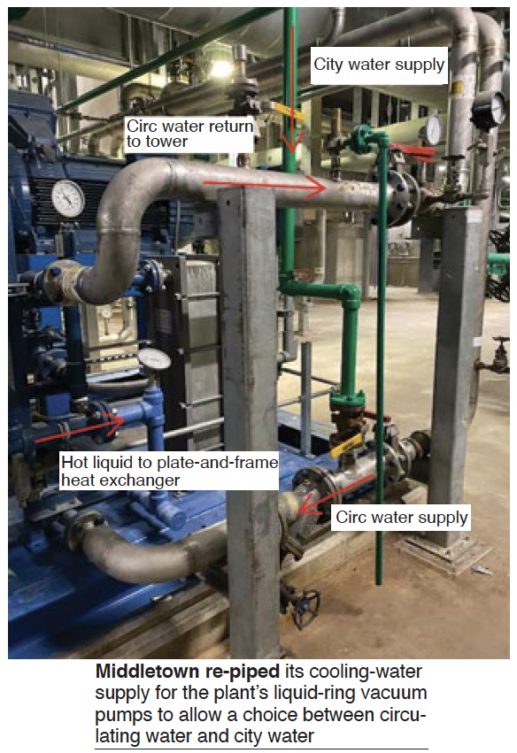
Staff responded by changing the cooling-water supply to the vacuum-pump skids—from circulating water to service (city) water. This modification did not increase water usage because the service water used on the vacuum skid was sent to the cooling tower as makeup.
Solution. To help alleviate the effects of pump cavitation and performance loss, and to minimize the need for personnel intervention, MEC piped service (city) water to the plate-and- frame heat exchangers on the vacuum skids. Using city water to cool the operating liquid stopped the cavitation and gained back some of the performance lost (photo). Circ-water temperature in summer is in the 90s; service (city) water is in the high 60s. Note that the circ-water line is still in place and can be used if needed.
Results. The plant estimates that an average of four man-hours per week is saved by using city water instead of circ water for pump cooling.
Project participants: Scott Ashley, Dan Truax, Dino Padilha
Plant cold-weather operations
Challenge. Middletown Energy Center faced no operational challenges during its first six months in the PJM market, achieving high reliability during that period. However, it faced freeze-protection issues during the first winter and tripped several times—adversely impacting plant performance. It was imperative that the plant identify and correct the problems to assure reliable and safe operation in future winters.
Looking into the issues that affected the plant during its first winter, staff identified the following four causes:
- Improper installation of insulation. Failing heat tracing.
- Improper heat tracing for the application.
- Inadequate monitoring to allow proactive action.
Once a problem occurred and the plant tripped, it was difficult for O&M personnel to identify all issues that had to be addressed quickly. Separating the problems and analyzing the issues, the plant identified the following main areas to focus on:
- Several heat-traced lines lost protection because the type of tracing used failed at high temperature. Thermostats were required to sense line temperature and turn off the tracing to avoid overheating. When the thermostats failed, the heat tracing turned off and the lines were left unprotected, leading entire lines to freeze.
- The instruments themselves had no temperature monitoring inside their boxes, so if the local heater failed, the transmitter would freeze, potentially leading to a plant trip.
- Several issues with the insulation itself rendered the installed heat tracing inadequate for some lines.
- After a problem occurred, there was no indication for the troubleshooting team to focus efforts to correct them.
- Boiler-feedwater-pump lube-oil heater was not able to maintain specified oil temperatures during cold days leading oil pressure to increase because of high viscosity, sometimes causing the pump—and possibly the plant—to trip.
Solution. Separating the issues in these areas, plant personnel started to define action plans to improve operations and prevent the problems from recurring. Heat-trace protection was the primary focus of staff efforts. Whenever a thermostat failed, an entire line would become unprotected leading to severe impacts on plant operations.
Plan was to replace the existing temperature-sensitive self-regulating (SR) cables with heat- tolerant mineral-insulated (MI) cables that did not require thermostat protection. Thus, heat tracing could be turned on and off based on ambient temperature. The new MI cables covered the tap-root connections of the instruments, assuring these areas also would be protected against freezing.
This was an extensive project with 55 lines (over 7000 ft) requiring upgrade of heat tracing, plus insulation. An additional benefit of the upgrade: Insulation of areas ignored by the original design.
After addressing the issues associated with heat tracing, thermostats, and insulation, staff provided operators the tools both to monitor the health of the heat-trace system while the unit is in service and to alert on possible problems by implementing capabilities incorporated into the plant’s Ovation asset management system (AMS). Note that the Ovation DCS operates in conjunction with Mitsubishi’s NetMation gas-turbine controls and Toshiba’s TosMap steam- turbine controls.
Standard information from a transmitter in the field is passed to the DCS system using 4-20- mA signals. Using the Hart communications protocol connected locally at each transmitter, the AMS signal can talk to all transmitters at specific intervals to gather more information—that is, instead of the transmitter just sending pressure, for example, it also tells you how healthy the transmitter is and much additional useful information.
This information is used primarily for obtaining temperatures within an instrument enclosure to warn of impending freeze conditions, possibly saving the plant from a hard trip. In addition to the newly created alarms, the plant also developed a DCS screen with alarm lights on a plant layout to advise operators where a given problem is located.
Despite the flexibility provided by the Ovation AMS, it does not cover the critical instruments connected to NetMation and TosMap that could potentially cause the plant to trip. To address this concern, the plant took the following actions:
- Installed alarm lamps on each transmitter box not covered by AMS. Each box was equipped with an ambient thermostat that will turn on the lamp to alert the auxiliary operator making rounds whenever the temperature inside the box drops below 40F.
- Revamped cold-weather rounds to include the checking of the transmitter boxes noted above, and scheduling rounds based on ambient temperature. The colder it gets, the more frequent the rounds.
The other area addressed was boiler-feedwater-pump lube-oil temperature control. The lube-oil tank was insulated with a custom-fit blanket to maintain desired oil temperature year-round. The plant also replaced the oil-heater assembly with one of a higher rating and designed to better distribute the heat throughout the tank and to prevent oil degradation.
Results. Although ambient temperatures at the plant site did not get as low as they did last winter, the thermometer dipped below 10F several times. However, no instruments froze as they had last winter. Plant availability increased significantly, achieving 100% in December, January, and February this winter, versus 94.3%. 78.5%, and 80.7% for the same months last year (excluding non-weather-related events).
AMS will be used to gather more operating information going forward. Plus, it will help maintain records of calibrations and will support the ability to conduct valve calibrations from the control room. Troubleshooting advice installed in the system will help solve problems quickly. It also will facilitate prioritizing work based on the criticality of the asset and the urgency of the alert. Finally, the AMS also will gather information to alert on issues before they become a problem.
Project participants: Ben Sumrall, Dan Truax, Dino Padilha.

Middletown Energy Center Owned by NTE LLC
Operated by NAES Corp
475-MW, gas-fired, 1 × 1 M501GAC-powered combined cycle located in Middletown, Ohio
Plant manager: Dino Padilha