By Steven C Stultz, Consulting Editor
CCJ’s reports on the last HRSG Forum with Bob Anderson and Australasian HRSG Users Group annual meeting discussed ageing issues associated with steam systems installed in the late 1990s and early 2000s, calling these combined-cycle and cogeneration facilities “pesky millennials.”
As these systems reach half-way in their design life, overheating of all components has become a growing concern. High operating temperatures and gas flow velocities are taking their toll. Outage inspections must become more refined.
A closer look
Things hidden. That’s the theme behind a series of diffuser-duct liner and insulation upgrade projects by HRST Inc, Eden Prairie, Minn. It is, of course, more complex than that. But HRST has found some driving concerns.
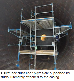
A common 7FA diffuser-duct inspection discovery is loose or broken studs, those components that secure the liner plates and C-channels within the casing. A typical diffuser-duct liner installation can have 1500 to 2000 (or more) studs. Traditionally, these studs are welded to scallop bars, imbedded in insulation, and, in turn, welded to the casing. The studs secure the liners, while allowing them to expand and contract with temperature changes (Fig 1).

The first key indicator of a problem is loose or broken studs, often 10 to 20 or more studs per inspection (Fig 2). Simply fixing the studs can become one of the final tasks during an outage. Crews do what they can with the time available.

As one owner/operator reports, “It starts with a few broken studs, and there’s never a real budget to fix that stuff. You do what you can.”
The result can be improper (incomplete) repair, perhaps more cosmetic than structural. As one field hand puts it, “You’ve got limited time to do 20 studs. So you weld them up and get out of there.” But the loose or broken studs could indicate something much more severe.
Another clear and related damage indicator is liner sheet fatigue cracks propagating from the stud holes (Figs 3 and 4).
Scallop bars and temperature
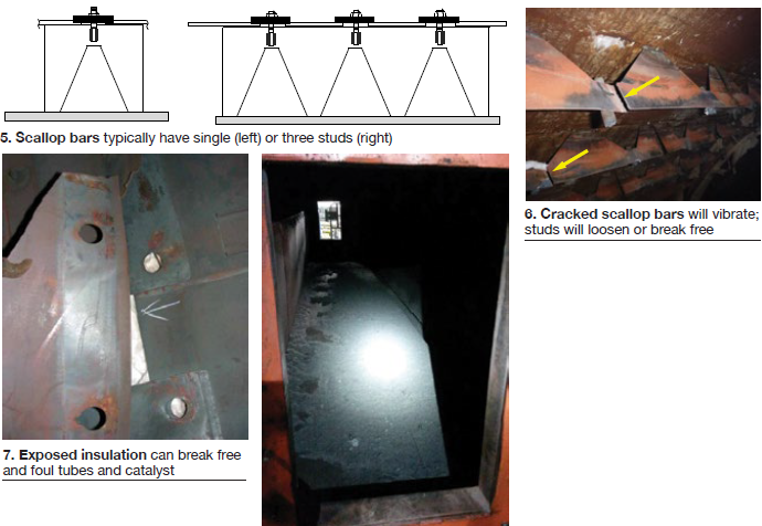
HRST has seen a lot of this. According to Rich Miller, site technical advisor for HRST, “Most scallop bars either are of the single-stud or three-stud design (Fig 5), and the duct designs we’ve changed out are predominantly scallop bars in segments of varying length.”
Discussing the effects of operations and temperatures, he explains “The bottom of the scallop bar welds to the casing and is buried in insulation. The top is where the studs attach, so there is a radical temperature difference between the bottom and the top.”
The top experiences typical 7FA exhaust temperatures of 1100F to 1200F. The bottom will be at 200F to 300F, or less.
Miller points out, somewhat in its favor, that “the scallop bar design works well—until the bars start breaking, as Fig 6 illustrates.” This is where both age and temperature change can create the problem, and cycling can accelerate the damage.

Most scallop bars are Type-409 stainless steel (same as most liner plates). The studs are Type-304 stainless steel, normally welded with more temperature-resistant Type 309. The expansion rates are not compatible and the welds fail. But the problems are not only with the welds. Once a scallop bar breaks, it vibrates. And for all diffuser-duct materials, fatigue strength decreases with temperature.
If plates and C-channels begin to work loose, insulation materials can be released and can foul the tubes and catalysts (Fig 7).
As Miller puts it, “The only way to know what’s going on under the liner is to tear it apart.” That’s precisely what HRST did at an installation in Iowa.
Experience
HRST’s first 7FA diffuser-duct redesign/retrofit was at a 2 × 1 system commissioned in 2004.
Stud failures began 2005, but the frequency increased steadily. By 2013, with the number of stud failures continuing to escalate, the owner/operator became concerned about possible scallop bar cracks hidden under the liner materials.
In 2015, one unit experienced liner-sheet liberation, causing a forced outage. The liberation led to immediate insulation fouling of the CO catalyst, and a backpressure jump of 4 in. H2O. Outage costs included both liner repair and catalyst cleaning, and operators became wary of repeat events.
The site had recorded stud repair data for each unit through each maintenance outage, and kept an accurate cost history. Upgrade justifications included annual stud and liner repairs, scaffold costs and time, backpressure-induced derates, catalyst cleaning costs, and a recognition that previous repairs were not addressing the root causes.
Owners ordered an upgraded diffuser-duct insulation and liner system from HRST, which had proposed eliminating the scallop bars. Instead, HRST would use one of its liner stud types, namely shoulder studs and square washers. In the end, the studs work “independently,” says Miller, which “removes the whole thermal expansion issue. The top of the stud does not care what the bottom is doing.”
Demolition began, and stripping off the old liner plates revealed that most of the scallop bars were either cracked or broken (refer back to Fig 6).
Future stud and liner failures were just waiting to happen, explains Miller. “Some might say a repair has lasted a couple years and they would hope to get another five out of it. I don’t think it works like that. Once the bars start breaking, the failure rate can radically increase. It could be twice as bad in two years instead of five.”
Pre-planning was important for both materials and contractor selection. Early award of liner design allowed installation drawings to be part of the contractor bid package, and materials were ordered months in advance. This reduced unknowns and potential supply issues, and allowed meetings to begin with the installation contractor.
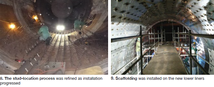
After demolition, crews supervised by HRST installed the bottom half of the liner first. Because the scallop bars had been eliminated, studs were welded to the casing one at a time in a density for heavy duty service (Fig 8).

Then, with the lower half complete, scaffolding was erected on the new liners and upper-half work began, first the studs, then the insulation, and finally the liner panels and corner angle (Fig 9).
“It’s a complicated geometry,” notes Miller, “round and tapered with an expansion joint to work around. It’s like a cone with the end cut off. And you can’t rely on the original drawings to get it just right. Early hands-on inspection and measurement are critical.”
The diffuser-duct sections at this site are unusually long (total 31 ft), but the process would have been the same for a more traditional 19-ft installation.
The first replacement, completed on schedule, has now been running since 2016.
Moving on
After these two units, HRST performed diffuser duct retrofits in Georgia then moved to Wisconsin, to a 2 × 1 7FA.03-powered combined cycle that began operating in 2004. Both units received diffuser duct replacements in 2018.
By this time, each HRST project had gained efficiency from experience. The first unit in Iowa was completed in three weeks working two shifts around the clock. The first Wisconsin unit was completed in about three weeks working one 12-hr shift. The second unit was completed in 15 working days, Monday through Friday, one 10-hr shift per day.
But the design had also changed.
“At the first Iowa unit we put the studs in one at a time. But in Wisconsin we decided to put these on a bar fabricated previously at a shop. The bars are however long they need to be, based on the geometry. The weld point in the field then becomes bar plate-to-casing.”
He continues: “The studs upstream to downstream are evenly spaced, but the distance in the lateral position upstream to downstream can be different stud-to-stud (perhaps a sixteenth of an inch). And the liner sheets reflect that. We pre-design and pre-make the liner sheets and stud bars, and the vast majority don’t need any trimming. There is just some custom fitting.”
Ya’ gotta’ listen
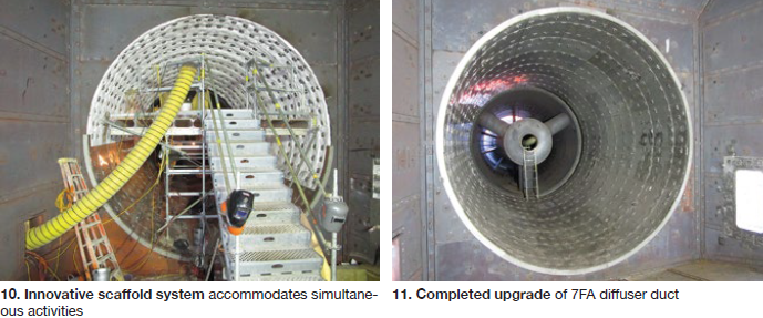
“A lot of the details become even more clear with experience,” reflects Miller “And at our most recent site we had a 28-year-old foreman, sharp as a tack, who wanted to show the world we could do this more efficiently.” The result was an innovative scaffold system that allowed multiple, simultaneous activities (Fig 10).

“They put some outriggers on the interior side of the duct,” explains Miller, “and they outfitted it so we could work on the top and the bottom at the same time. This was huge!”
“It’s like a suspended scaffold,” noted the owner/operator. “You can work top and bottom at the same time, and there’s room to get more people in there than you would think.”
This innovation was used on both Wisconsin units.
“Each job is contractor-dependent, and you need to listen to everyone’s ideas,” states Miller.
Technical advice
Attention to detail is critical. “No single operation of the installation by itself is all that complicated, but there is a learning curve to each one. Secondly, there are always unique minor issues that require solutions you want blessed along the way,” stresses Miller.
And even with the best installation contractor, he continues, “there’s enough going on that you need a technical advisor out there.”
The editors then asked if this retrofit was unique to the 7F machines. “I can’t imagine why it wouldn’t work in a 7EA, likely a Frame 6, or really anything,” said Miller. “And if it needs to be bigger, we’ll make it bigger.”
HRST has gained some experience performing various isolated in-kind repairs of the scallop bar design, but sees some benefit in their removal. “I think this is the way to do it,” suggested Miller. “It’s what I would do.”
Miller has been HRST’s field installation supervisor and technical advisor on several of these projects, and obviously takes great pride in what his company and the plant-selected site crews have accomplished.
And after discussing the latest project (Fig 11), he summed it up: “These jobs are some of the most rewarding due to the final visuals when complete. In that last five minutes before I throw my hard hat in the bag and go home, I’ll stand there, take a few pictures, and think ‘Wow… I had a big part in this.’ And you see the same thing with the contractors, and the site personnel.” CCJ


