Turbine Tip No. 4, contributed by PAL Turbine Services’ Owner/GM Dave Lucier, applies to General Electric Frame 5 models K, L, and LA. The focus here is on fuel pumps that are retained when the control system is upgraded.
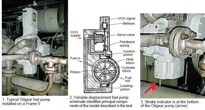
The fuel pump of choice on GE gas turbines following the Great Blackout of November 1965 was Oilgear model PVAZKM-054 (Fig 1). When users consider upgrading the control system on these 50-year-old gas turbines, prospective contractors often tell them that they can retain the existing fuel pump. This often is done one of two ways:
-
- The Oilgear fuel pump can be modified to “fully stroke” it, such that a bypass valve can be installed to control fuel flow to the combustors. Since the existing flow divider from Roper Pump Co does not have speed pickups to measure fuel flow, that device must be replaced as well, so there is not much cost saving.
- Remove the existing Young & Franklin fuel regulator, but retain the constant control oil (CCO) pump to maintain the 300-psig source working pressure. Then install a modern signal actuator with a control range of 4- to 20-milliamps input for 40- to 200-psig control signal output. In this case, the Oilgear fuel pump would continue to work as it had for the previous five decades with the same flow divider.

Note that in this article, the control signal is called VCO—for variable control oil pressure (Fig 2).
Fig 3 shows an indicator protruding from the bottom of the fuel pump (red arrow). It displays the pump stroke. From the GE control specifications in Fig 4, read the pump stroke for an unmodified unit: VCO = 40 to 200 psig results in total stroke of 0 to 0.320 in. The first 40 psig is referred to as the zero effective stroke.
To measure the pump stroke at turbine “cranking” speed (1000 rpm), a precision machinist’s rule is recommended, because a dial indicator often vibrates excessively. The confusing part of checking the pump stroke with a ruler is that the stroke indicator “disappears” upward into the pump, as the VCO pressure goes from 0 to 200 psig. Thus, you must take an initial reading of the exposed indicator and then again when selecting the MAX VCO on selector switch 43FS inside the turbine control panel.
PAL recently visited a plant to do a GEMAC replacement for a customer with an MS5001L engine. The team asked if they could first “crank” the gas turbine to take some readings regarding the fuel regulator, including maximum VCO. This is a typical test done to establish some primary adjustments and observe the fuel-pump stroke.
The owner/operator was told that PAL could measure fuel-pump stroke with a precision ruler that read in 1/32-in. increments. While cranking the turbine, it was observed that the pump-stroke indicator did not move upward into the pump body.
The PAL team ran the turbine up to 100% speed (FSNL), expecting a VCO pressure of about 80 to 85 psig, as indicated on the last line of the spec sheet in Fig 4. But it was 111 psig, much too high. Recall that fuel flow is a function of both pump speed and stroke. At constant speed (100% FSNL), therefore, an increase in VCO results in an increase in fuel flow (linear to VCO value).
To fully understand pump design, you must subtract 40 psig from pressure readings on the VCO gage. Thus, the expected reading was 80 – 40 = 40 effective VCO. In this case, 40 was subtracted from 111 to get 71 psig. Thus, it was taking far more pump stroke to run the turbine at rated speed than expected from the data in the GE control specifications. PAL’s conclusion: The pump was failing.
The team suggested that some of the pump’s 26 internal pistons likely were stuck in position and not pumping fuel. Disassembly and inspection revealed eight stuck pistons. The owner/operator agreed with PAL that the pump should be replaced with a rebuilt one.
The bottom line: A test is worth 1000 “expert” opinions. Test the Oilgear fuel pump at crank speed before you consider reusing the variable-displacement fuel pump following a control-system upgrade. Don’t assume it is operating correctly after 50 years of service.


