

With the 2024 HRSG Forum fast approaching in June, have a look at the breadth of topics and discussion points covered at last year’s event during the end user presentations, featured here, and all the other components of the conference. The 2023 HRSG Forum event in Atlanta, the organization’s first physical meeting since the Covid interruption, established the current four-day in-person format, encouraging all attendees to participate in the following:
- Cycle Chemistry Workshop—Film-forming substances
- Materials Workshop—Welding and metallurgy
- General Session presentations by Users
- General Session presentations by service providers
- EPRI Technology Transfer Workshop
HP evaporator replacement
Yogesh Patel, Tampa Electric/TECO, and Vignesh Bala, Vogt Power, gave a detailed, experience-based presentation on the replacement of HP evaporators for the two combined cycles at the 1800-MW Bayside Power Station, Unit 1 (3 × 1) and Unit 2 (4 × 1), commercial since 2003 and 2004, respectfully. The units are equipped with GE 7FA gas turbines and Alstom HRSGs.
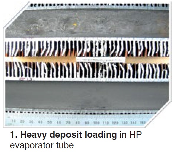
In December 2016, the station incurred several HP-evaporator tube failures in two of its seven HRSGs. All experienced under-deposit corrosion. Failure analysis indicated significant amounts of deposit weight density (DWD) within the tubes. The first sample showed the loading at 154 g/ft2.
In 2018, borescope inspections at Unit 2 showed a concentration of debris within the front headers and within the tube bundles approximately 18 to 20 in. above the bottom header. Tube leak-location experience was then analyzed. Tubes were removed (Fig 1) showing heavy deposit loading and wall-thickness issues.
 Replacement decisions were made. Bala discussed planning, detailed design, fabrication, delivery, and construction. TECO selected Grade T11 tubes with carbon-steel fins and elected to fabricate in the US (Boiler Tube Company of America/BTA) for schedule and ease of inspections.
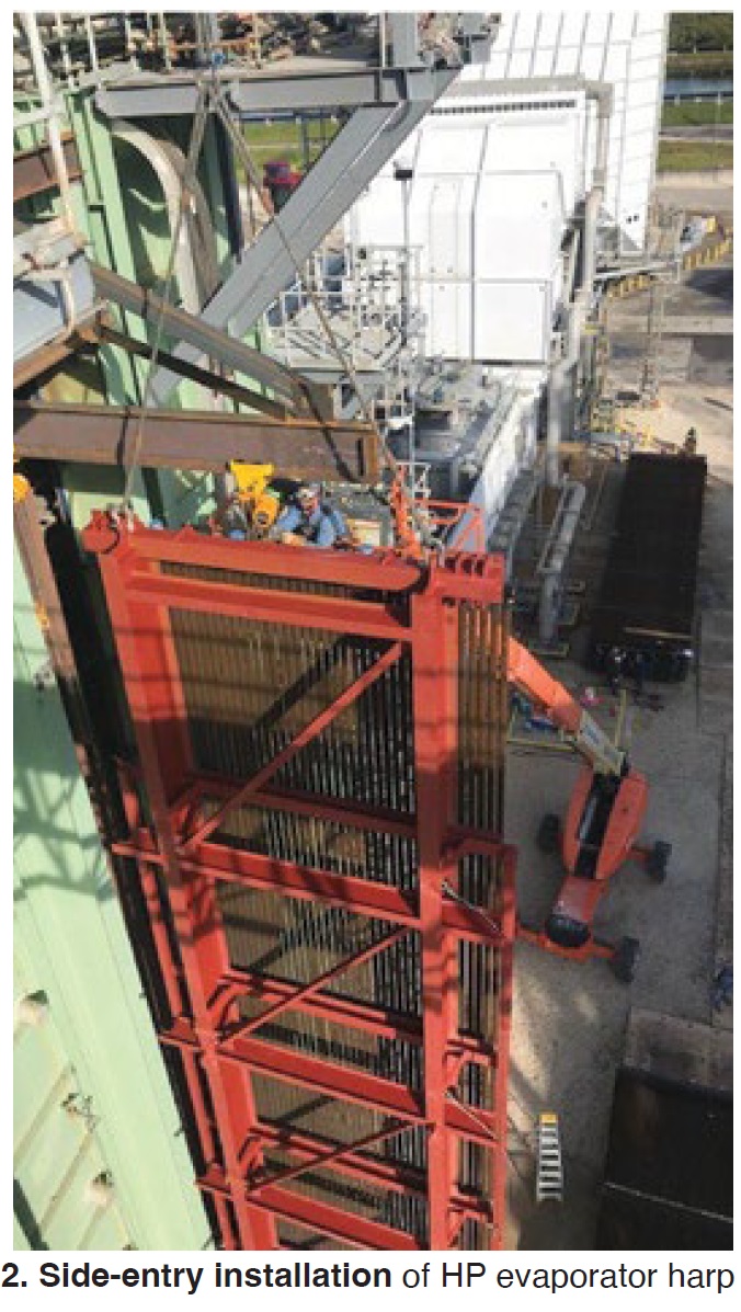
Preliminary construction planning considered both side and top access. Top entry was not effective because of the drums, so TECO selected the individual-lift side-entry option. The power producer also selected in-shop hydro with authorized inspection to ensure the integrity of welds and conduct any repairs before delivery.
“Demolition was one of the most challenging parts of the construction phase,” explained Bala. Harps were severed and removed.
“Coordination within the last 100 ft is critical; new harps must be delivered in the proper sequence!”
Installation included 48 individual harp lifts using one handling frame and one up-righting frame. A monorail system was used to slide the harps into the HRSG (Fig 2). Welding and NDE followed.
Post-presentation questions and discussions focused on the benefits of removing HP evaporator tube samples and having them analyzed for internal deposit loading, the impacts of poor long-term water chemistry, and the need to monitor for total iron.
HRSG damage monitoring
Duke Energy and Structural Integrity Associates (SI) jointly discussed online monitoring—more specifically a unique HRSG damage monitoring system. Presenters Eugene Eagle (Duke) and Kane Riggenbach (SI) looked at real-time assessment of system performance and component integrity for both HRSGs and high-energy piping.
Their example: Duke’s 920-MW H F Lee Energy Complex, a 3 × 1 combined cycle (commercial 2012) anticipating future cycling requirements (Fig 3).
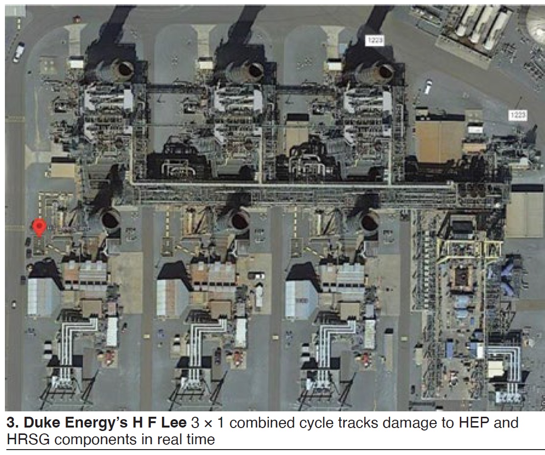
The Siemens F-class gas turbine/Vogt triple-pressure HRSG units at Lee have accumulated nearly 70,000 hours and have had damage issues related to RH and HP attemperation. “Many SH/RH drain, operational, CT exhaust, and attemperator control logic changes have been implemented,” explained Eagle. Current operation is baseload, with low-load turndown to 40 MW per gas turbine.
They began with an interesting HRSG overview, adding that each unit has surface-mounted, thermocouples of an advanced design that were installed at commissioning. It showed components typically susceptible to creep, fatigue, creep-fatigue interaction, corrosion fatigue, oxidation, and exfoliation. The focus (16 areas per unit) includes interstage and bypass attemperators, intermediate headers and tubing downstream of attemperators, branch connections, final-stage outlet headers, and drums.
Structural Integrity provided and monitors the PlantTrack™ system installed after 70,000 service hours.
Program goals are early detection when rate of damage is rising, and prioritizing locations and systems with a long-term goal of extending inspection intervals. Data can also be used to assess accuracy of fitness-for-service assumptions and adjust recommendations.
Specific life-management benefits include detection of operational or process changes (failed nozzles, leaking valves, etc) and evaluations of control logic changes (valve opening, spray amounts, etc). Comparison of operating modes (and impacts on component life) are made between units and plants, for low-load operations, operating with and without steam sparging, and for changes in startup times.
Riggenbach explained damage trending saying that “when monitoring, a time series of damage will be created,” then adding that “a historical rate of damage consumption can be extrapolated.” Previous inspections can be used as benchmarks. With this, future projections of damage consumption can be made (Fig 4).
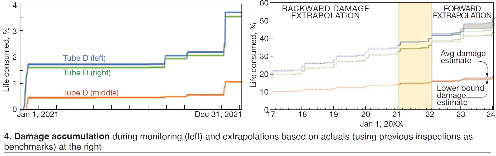
Various examples of data presented on the PlantTrack Dashboard also were provided.
Duke’s plan is to develop trends and translate the data for sister units.
The presentation generated many questions, comments and discussions. Placement of thermocouples (total of 128) was further explained. Other comments focused on thermocouple attachment (EPRI method used), the security hurdles of sending live data away from the site, the possibility of using the data for faster startups, and using the data to estimate remaining life of piping.
Attemperator repairs
Al Olszewski, Constellation Energy, reviewed fleet-wide Attemperator inspections and repairs. This non-plant-specific presentation covered selected issues with various attemperators, including:
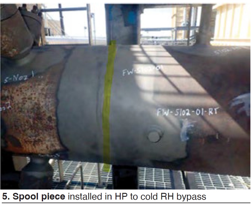
- High-pressure (HP) to cold-reheat bypass. Fig 5 shows internal indications at downstream girth-weld (P91 material). Girth weld was machined out and repaired with spool piece.
- Intermediate pressure interstage (vertical). Significant quench-cracking of liner was revealed. Inspection is ongoing; a spare now is available onsite.
- Hot reheat interstage (vertical). The liner liberated after 68k hours and was repaired with liner pins.
- HP interstage. A P91 nozzle liberated at weld after 35k hours. Thermal-mechanical fatigue was cited as the cause. Opening was rounded to reduce stress.
- Hot-reheat bypass to condenser. Repeat cracking of upstream and downstream girth welds after 45k hours. Now monitoring for thermal fatigue.
Many similar case histories and repair solutions were discussed after the presentation, stressing the need for frequent and complete testing (including addition of thermocouples). The benefits of proper clearances and use of OEM parts in critical applications also were mentioned.
HRSG tube failures
The Qurayyah Combined Cycle Power Plant in Saudi Arabia comprises multiple blocks, each 3 × 1 with GE 7FA.04 gas turbines and GE D11 steam turbines. The unfired triple-pressure HRSGs are Doosan and CMI vertical-gas-path units.
Ghazi Al-Shammari discussed HRSG tube failures and consequences. He walked through the plant’s background, then focused on the tube failures in one unit that became apparent in 2016 (high water consumption, noise, and steam emitted from the main stack).
All tubes and headers were visually inspected. Tube defects were found at 19 locations near the hot-reheat header. Thermal-fatigue cracking also was apparent close to the tube-to-header welds (Fig 6).
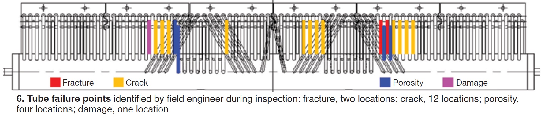
The speaker walked through the various damage mechanisms found and then the root-cause graphic depiction of thermal stresses.
Recommendations made based on plant experience were these:
- After each HRSG shutdown, ensure all TCVs/bypass MOVs and inlet isolation MOVs are closed.
- Follow normal startup procedures and physically verify all valve positions, both open and closed.
- Watch for any abnormal valve behavior—including noise, vibration, or temperature change.
- All manual drain isolation valves should be open at all times.
- All drain MOVs should be on auto at all times.
- Operators should physically monitor drain-valve levels and differential temperatures at all times.
Qurayyah has reduced (1) annual forced outages attributed to tube leaks from five to one, (2) water consumption, and (3) tube metal temperatures.
Discussions and suggestions followed on numerous issues—including the following:
- Manual bypass around the attemperator block and control valve (should be removed).
- Spray-valve operation and maintenance.
- Inability to drain RH and SH tubes (in this design).
- Proper and improper use of dampers.
- Tube failure-analysis options—including removal, accuracy of data programs, and root- cause/damage mechanism distinctions.
Valve maintenance program
Bernard Frezza, Athens Generating, operated by NAES, discussed the Valve maintenance program at the 1080-MW plant with three 1 × 1 combined cycles equipped with Siemens 501G gas turbines, Nooter/Eriksen HRSGs, and Siemens HE steam turbines.
Athens did not have a valve monitoring program when commissioned in 2004. Work orders were put in by staff if a valve had visible failure, noise, or leaks. The plant learned over time that this reactive approach led to unplanned maintenance, costly repairs, and outages.
Athens has been working with Millennium Power Services since 2017 to track and prioritize valve maintenance, and bring their program up to industry standards through a proactive approach. One benefit is “improved heat rate through reductions in water and steam losses,” said Frezza.
Millenium keeps records and maintenance interval data, and plans for future inspections based on plant budget and needs. Each valve has an associated report.

Athens uses Millenium’s TrimKit™ program to reduce costs and labor, and to provide all new parts for specific valves. Refurbished parts can be returned to the kits (Fig 7).
Millennium now offers Athens a 10-yr plan, revised as necessary.
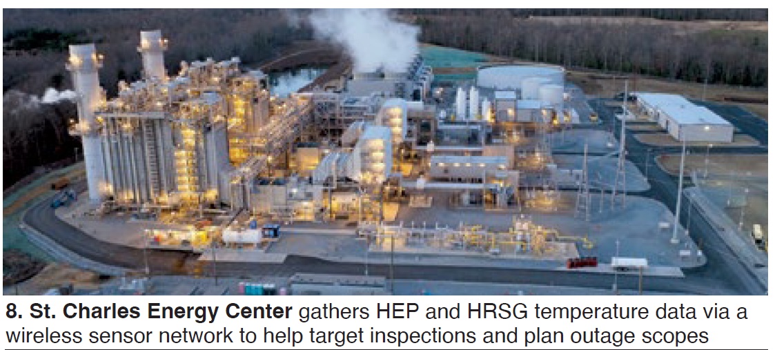
Wireless HEP program
CPV’s St. Charles Energy Center in Maryland (Fig 8) has implemented a wireless high-energy-piping (HEP) program, which was described by Jacob Boyd. Background: The 745-MW plant, commissioned seven years ago with two GE Fast-Start 7FA.05 gas turbines, one GE D-11A steam turbine, and two CMI HRSGs, typically cycles from 140 to 170 times annually.
Near the end of 2019, one HRSG suffered a through-wall leak at a girth weld on a hot reheat (HRH) steam-to-condenser bypass line. The failed weld was removed and sent to Structural Integrity (SI), finding that thermal fatigue was the most likely cause.
“Plant personnel worked with SI to install thermocouples around the area to assess the magnitude of thermal transients during load changes and normal operations,” explained Boyd. Significant temperature variations around the pipe circumference (up to 700 deg F) were noted during load-change events. SI data were sent to the OEM who redesigned the HRH bypass attemperator spray-nozzle assembly. Plant staff modified the attemperator logic.
The plant had only been operational for two years, and “plant staff was concerned there may be other unknown high-energy piping issues that could fail prior to regularly scheduled inspection,” said Boyd. “Working with Structural Integrity, a solution was proposed to install a wireless sensor network and thermocouples to remotely read data in near real-time and incorporate the readings into St. Charles’ PlantTrack online database.”
SI performed a risk-ranking prioritization known as Vindex™ (Vulnerability Index) that considers factors such as creep life, Grade 91 risk factors, consequence of failures, etc, and assesses each weld or location of interest according to damage potential. The plant then installed thermocouples at 10 different locations throughout the HEP system, plus nine online pipe-hanger monitors.
Data were used for the spring 2023 outage. Online monitoring of the HRH bypass had shown five high events and 155 medium events. Field results in 2023 then identified multiple ID and OD indications. A spool piece was needed and installed.
Said Boyd, “the system is a highly valuable tool to target inspections and plan outage scopes. We now have improved plant safety and reliability, while reducing O&M costs and the potential for lost generation.”
Chemistry and corrosion, user survey results
Barry Dooley, Structural Integrity (UK), presented the latest international statistics on cycle chemistry and FAC, summarizing results from 270 combined-cycle and fossil plants. He began with the following observation: “It looks like hydrogen damage/under-deposit corrosion is increasing around the world. This is a big issue!” He would soon return to this topic, discussing repeat cycle-chemistry situations (RCCS).
Dooley first reviewed chemistry-influenced tube failure damage and failure mechanisms, corrosion-product transport attributed to inadequate feedwater low-pressure circuit chemistries, and steam turbine deposits/damage/failures.
For the latter, leading current steam-turbine damage mechanisms are:
- Corrosion fatigue of blades and discs in the phase transition zone (PTZ) of the LP turbine.
- Stress corrosion cracking of discs in the PTZ.
- Pitting (initiator of damage).
- Liquid droplet erosion.
- Flow-accelerated corrosion.
- Deposition.
He reviewed the repeat cycle-chemistry situations found in the assessments, then focused on hydrogen damage and internal HP evaporator deposits as an example.
Dooley noted that the International Association for the Properties of Water and Steam (IAPWS) would soon publish a procedure to quantify corrosion-product transport during startup. He called this an “exciting development” and summarized the procedure:
- Flush feedwater sample point as soon as pressure is available.
- Measure and register oxide levels in feedwater by proxy methods during startup.
- Take samples for filtered iron intermittently to establish a correlation to proxy results.
- Note times for milestones: first fire, bypass, turbine rollup, synchronization, etc.
- Plot iron levels versus time after first fire and mark milestones.
- Integrate (iron level, feedwater flow) from first fire to steady state level; iron transported to boiler during startup.
He then turned to both single- and two-phase FAC, which he said are “still occurring worldwide and not being identified properly” as they do not share the same mechanisms.
Looking for single-phase FAC evidence in HRSGs he offered a few interesting notes, including “things to look for”:
- Level of oxygen at condensate-pump discharge and boiler feed pump.
- Color of LP and IP drums for “ruggedness of redness.” Red appearance will be “patchy” with grey magnetite showing through when oxidizing power is “low.”
- Levels of iron (“Rule of 2 and 5”): Less than 2 ppm total iron in condensate/feedwater, less than 5 ppm in evaporators/drums.
His concluding reminder: resources for all areas of water and steam are freely available for review and download at www.iapws.org.
Open discussion
A sampling of questions and discussion topics submitted to the HRSG Forum as part of the registration process included these:
- What are the best practices for welding carbon-steel tubes to headers (including inspections)?
- Poll: How many users are taking HP evaporator deposit-density tube samples?
- Tube sample methods and locations were discussed, initiating discussions on chemical cleaning and under-deposit corrosion.
- HRSG tube-plugging impact on hydraulic flow characteristics led to discussions on (1) tube temperature changes, and restorability of abandoned tubes, (2) inventory of spare tubes retained onsite, including filler metals; and (3) experiences with tube repair versus plugging. Interesting comment from Bob Anderson during this exchange: If you plug, you don’t know the failure mechanism and root cause to reduce chance of repeat failures.
- Best practices for boiler feedwater pumps and control valves for controlling HP-drum levels led to discussions on attemperators and valves.
- Drum-level trips related to instrumentation and controls.
- Repair experience with attemperator nozzle bore hole cracking.
- Duct-burner replacement: Determining the need, timing, and material options.