The AOG looks ahead to its sixth annual meeting, March 20-24, at EPRI’s corporate offices and training facility in Charlotte, NC. This will be the organization’s first in-person conference since 2020. A preliminary 2023 conference agenda is posted at www.aogusers.com, where you’ll also find registration, lodging, and other pertinent information. Contact ashley@aogusers.com with any questions.
This is the second and final part of CCJ ONsite’s AOG 2022 coverage and includes what can amount to a comprehensive overview of the Alstom aftermarket. Its primary focus is what the third-party vendors had to say about their shop facilities, products, and services for the Alstom fleet. Summaries of the training workshops conducted by Liburdi Turbine Services and National Electric Coil also are provided. Registered users can access presentations of interest on the organization’s website. Follow these links to access the coverage:
- AOG 2022: Gas turbine aftermarket robust and ready for challenges facing Alstom fleet
- AOG 2022: Steam turbines come into focus with age and new opportunities
- AOG 2022: Generators continue to be a thorn in side of owner/operators
- AOG 2022: Training workshops focus on GT failure analysis and generators
The first part of CCJ’s coverage of the 2022 AOG can be accessed here:
- AOG 2022: Alstom user discussion and in-depth presentations illustrates value of attending upcoming in-person event
- GE Day at AOG 2022 updates Alstom user community on TILs and upgrades for major CCGT equipment
AOG is a private user organization that enables owner/operators of Alstom equipment to communicate directly with each other, and with third-party services providers, in a secure setting. Membership is limited to individuals directly involved in the construction, operation, and/or maintenance of Alstom gas and steam turbines and who are employed by companies with ownership and/or operational interest in those turbines.
Content for, and conduct of, AOG conferences is organized by a steering committee, with the following members for 2023:
- Brian Vokal, VP operations and engineering for Midland Cogeneration Venture.
- Pierre Ansmann, global head of marketing for Arnold Group.
- Robert Bell, plant manager of Tenaska Berkshire Power.
- Jeff Chapin, AOG founder, Liburdi Turbine Services.
- Ross Goessl, PE, senior engineer for We Energies.
Note that Goessl replaces Southern Company’s Chris Hutson, a founding board member and major contributor to the group’s success. Hutson resigned in early November, having transferred from the user community to K Machine Industrial Services.
February 19–23, 501F Users Group
Annual Meeting, Reno, Nev, Peppermill Resort & Spa. Details/registration at www.501fusers.org as they become available. Chairman: Ivan Kush, Cogentrix Energy Power Management. Contact: Jacki Bennis, jacki@somp.co.
February 19-23, 501G Users Group
Annual Meeting, Reno, Nev, Peppermill Resort & Spa. Meeting is co-located with the 501F Users Group conference. Details/registration at www.501fusers.org as they become available. Contact: Jacki Bennis, jacki@somp.co.
March 12-15, Western Turbine Users Inc
33rd Anniversary Conference and Expo, San Diego, Calif, San Diego Convention Center. Details/registration at www.wtui.com first week of January. President: Ed Jackson, Missouri River Energy Services. Contacts: Charlene Raaker, conference registration coordinator, craaker@wtui.com; Wayne Kawamoto, conference executive director, wkawamoto@wtui.com.
March 20-24, AOG (Alstom Owners Group) Users Conference
Sixth Annual Meeting, Charlotte, NC, EPRI Campus. Details/registration at https://aogusers.com. Contact: Ashley Potts, ashley@aogusers.com.
March 21-23, Film Forming Substances
Sixth International Conference, Prato, Italy (about 20 minutes by car or train from Florence), Monash University. Details/registration at https://FilmFormingSubstances.com. Chairman: Barry Dooley, Structural Integrity Associates (UK). Contact: Rachel Washington, rachel@meccaconcepts.com.au.
April 23-27, CTOTF
Spring Conference and Trade Show, Greenville, SC, Hyatt Regency Greenville. Details/registration at www.ctotf.org. Chairman: Dave Tummonds, LG&E/KU. Contact: Chris Doyle, executive vice chair of operations, chrisdoyle@ctotf.org.
May 15-19, 7F Users Group
2023 Conference and Vendor Fair, Atlanta, Ga, Renaissance Atlanta Waverly Hotel & Convention Center. Details/registration at https://www.powerusers.org as they become available. Contact: Sheila Vashi, sheila.vashi@sv-events.net.
May 16-18, European HRSG Forum
Ninth International Conference, Prato, Italy (about 20 minutes by car or train from Florence), Monash University. Details/registration at https://europeanHRSGforum.com. Chairman: Barry Dooley, Structural Integrity Associates (UK). Contact: Rachel Washington, rachel@meccaconcepts.com.au.
June (dates TBA), ACC Users Group
Annual Conference, Richmond, Va. Details/registration at https://acc-usersgroup.org as they become available. Chairman: Andy Howell, EPRI. Contact: Sheila Vashi, sheila.vashi@sv-events.net.
June 5-8, Siemens Energy Large Gas Turbine Conference
(formerly the Siemens Energy F, G & H Conference, now including tracks for 251B10-12 and 501D5-D5A units), Orlando, Fla, Renaissance Orlando at SeaWorld. Details/registration information expected in mid-February. Contact: Dawn McCarter, dawn.mccarter@siemens-energy.com.
June 6-8, D5-D5A Users Group
2023 Conference and Vendor Fair, Chattanooga, Tennessee. Details/registration information expected soon at 501D5-D5A Users website. Contact: Gabriel A. Fleck, P.E., 501D5-D5A Users Chairman, chairman@501d5-d5ausers.org
June 12-15, HRSG Forum
2023 Conference and Vendor Fair, Atlanta, Ga, Renaissance Atlanta Waverly Hotel & Convention center. Details/registration at https://www.powerusers.org as they become available. Chairman: Bob Anderson, Competitive Power Resources. Contact: Sheila Vashi, sheila.vashi@sv-events.net.
July 17-20, Legacy Turbine Users Group
Second Annual Conference and Vendor Fair, Chandler, Ariz, Sheraton Grand at Wild Horse Pass. The Frame 5, 6B, and 7EA Users Groups comprise LTUG and meet independently; some joint functions, including meals and vendor fair. Details/registration at https://www.powerusers.org as they become available. Contact: Sheila Vashi, sheila.vashi@sv-events.net.
July 23-27, Ovation Users’ Group
Annual Meeting, Pittsburgh, Pa, The Westin. Details/registration at www.ovationusers.com as they become available. Contact: Anne Turkowski, anne.turkowski@emerson.com.
August (dates/location TBA), HA Users Group
2023 Conference serving owner/operators of GE 7HA and 9HA gas turbines. Chairman: Michael Banks, DTE Energy. Details/registration at www.powerusers.org as they become available. Contact: Sheila Vashi, sheila.vashi@sv-events.net.
August 28-31, Combined Cycle Users Group
2023 Conference and Vendor Fair, Atlanta, Ga, Omni Atlanta Hotel at CNN Center. Meeting is co-located with the Steam Turbine, Generator, and Power Plant Controls Users Groups, and the Low Carbon Peer Group; some joint functions, including meals and vendor fair. Details/registration at www.powerusers.org as they become available. Contact: Sheila Vashi, sheila.vashi@sv-events.net.
August 28-31, Steam Turbine Users Group
2023 Conference and Vendor Fair, Atlanta, Ga, Omni Atlanta Hotel at CNN Center. Meeting is co-located with the Combined Cycle, Generator, and Power Plant Controls Users Groups, and the Low Carbon Peer Group; some joint functions, including meals and vendor fair. Details/registration at www.powerusers.org as they become available. Contact: Sheila Vashi, sheila.vashi@sv-events.net.
August 28-31, Generator Users Group
2023 Conference and Vendor Fair, Atlanta, Ga, Omni Atlanta Hotel at CNN Center. Meeting is co-located with the Steam Turbine, Combined Cycle, and Power Plant Controls Users Groups, and the Low Carbon Peer Group; some joint functions, including meals and vendor fair. Details/registration at www.powerusers.org as they become available. Contact: Sheila Vashi, sheila.vashi@sv-events.net.
August 28-31, Power Plant Controls Users Group
2023 Conference and Vendor Fair, Atlanta, Ga, Omni Atlanta Hotel at CNN Center. Meeting is co-located with the Steam Turbine, Generator, and Combined Cycle Users Groups, and the Low Carbon Peer Group; some joint functions, including meals and vendor fair. Details/registration at www.powerusers.org as they become available. Contact: Sheila Vashi, sheila.vashi@sv-events.net.
September 24-28, CTOTF
Fall Conference and Trade Show, Prior Lake, Minn, Mystic Lake Casino Hotel. Details/registration at www.ctotf.org. Chairman: Dave Tummonds, LG&E/KU. Contact: Chris Doyle, executive vice chair of operations, chrisdoyle@ctotf.org.
If you were unable to sit in on the second day of the 2022 AOG conference and want to hear what the OEM of record (GE) had to say, access the three-hour recording via the links provided in the last paragraph of this section. It is highly recommended to review the following in anticipation of the upcoming 2023 AOG in-person event in Charlotte, NC, March 20-23.
Given that three hours is a big bite out of anyone’s day, the editors recommend fast forwarding through the first hour and selecting the parts you want to hear using the summary below as a guide. Our guess is that you can listen to everything pertinent to your responsibilities over a typical desk-top lunch.
What’s in the first hour? The challenges of the post-Covid world regarding supply-chain issues, stretched-out delivery times for capital parts, the need for better advanced planning, GE’s planned reorganization into three companies, lessons learned, contingency plans, safety initiatives, cross training of personnel to alleviate some training challenges, and on, and on.
Steam turbines
Recently released technical information letters (TILs) pertaining to Alstom steam turbines followed the long intro:
TIL-2052, KA24 ICS steam-turbine IP rotor cracking.
Some significant indications have been found during recent inspections of KA24 steamers. Of the dozen-and-a-half rotors inspected in the time period addressed, half had indications. TIL-2052 was updated to reflect these findings—one a particularly deep crack caused by creep-fatigue interaction. Interestingly, no abnormal vibration behavior was observed by plant personnel when the turbine was operating.
Root cause analysis (RCA) concluded cracking risk depends on the following, among other causes:
- Number of starts and the mixture of hot/warm/cold starts.
- Low steam temperature on hot starts.
This TIL requires rework in the P1, P2, and P3 piston areas at 800 starts, plus operational changes to reduce life consumption.
TILs also have been released recently for units with configurations similar to those of the KA24: 2205 and 2230, equivalent-cycles based, and 2315 and 2316, equivalent-hours based (EOH). These have different equivalent limits and specific inspection and rework requirements based on the lifetimes of limiting features. Attendees were asked to work with their respective GE service reps to assess the current level of equivalent cycles or operating hours, whichever applies. Get the details in Slide 35.
TIL-2010, Radial inlet vane (Radax).
Inspections have revealed findings on high- and intermediate-pressure turbines with radial inlet scrolls (Radax)—specifically: bent, partially cracked, and in a few cases, fully cracked/ruptured airfoils.
TIL recommends regular borescope inspections to determine if a problem exists. Particularly important is to borescope about a year before the next major—a/k/a C-inspection—to see if there’s any cracking (such as at airfoil fillet radaii) that requires new parts so these can be ordered before time becomes an issue, and a casing lift can be incorporated into the outage plan.
This TIL was released in 2017 and since that time findings have been identified in about 20% (round numbers) of the units inspected. A chart presented shows that operating hours and temperature influence component condition.
TIL-2360, Potential for austenitic-blade root cracking.
This document is less of concern for combined-cycle units than the TILs mentioned previously. It applies to high-use units with austenitic blade material in the inlet stages. Recent work by the OEM revealed that the underlying root cause of the cracking was creep damage.
Note that “high utilization” is determined by a review of operating history. If it is in evidence, blading should be replaced at the next overhaul with a lower-utilization configuration to help mitigate the risk of premature creep.
TIL-2266, Valve tooling replacements.
The OEM learned that tooling being supplied to remove steam-turbine valve internals could yield under appropriate working loads, posing a risk of personnel injury and/or product damage. Recommendation: Replace tooling with improved capability and function prior to your next scheduled outage.
The TIL segment of the program finished with a look at what “damage” can occur to a steam turbine during periods of low load and cycling. This is particularly helpful in operational decision-making. Here are the damage mechanisms to be aware of:
- Inlet valves—throttling and solid-particle erosion.
- HP and IP shells and valve casings—low-cycle fatigue (LCF).
- HP and IP rotors—LCF.
- HP and LP sections—windage heating.
- Casing and last-stage blades—erosion when hood sprays are on.
- Last-stage blades—LCF.
Presentations on other steam-turbine topics made after the steamer TIL updates:
Parts planning is particularly important today, the group was told, given the long lead times associated with replacement capital components. The speaker pointed out that many steam turbines are unique from Day One and some parts must be made—often there are no spares on a warehouse shelf. A review of a given unit’s lifetime operational history, a collaborative effort between the OEM and owner/operator, is critical to proper planning.
GE’s next-gen steam-turbine valve portfolio was next on the agenda. New valve internal geometries and materials are said to improve component reliability and operability. More specifically: reduced risk of stem leakage and valve sticking, increased throttling range, and ability to accommodate low load and daily starts.
These valves are designed for as little as 25 hours of operation per start, half of what had been recommended previously and more in synch with the operating paradigm forced on many combined cycles today. Another advantage of the durable next-gen valves is that their maintenance can be done on a C-inspection schedule rather than during B inspections.
Gas turbines
Options for decarbonizing gas power, a topic at most—if not all—power-industry conferences these days, looked at both pre- and post-combustion solutions. For the former, the following zero- or low-carbon fuels were reviewed: hydrogen (blue, green, pink), synthetic methane, renewable methane, biofuels, and ammonia. Carbon capture by way of liquid solvents or solid sorbents in the exhaust stream, and oxy-fuel cycles, were the post-combustion processes discussed.
Alstom experience burning hydrogen in gas turbines, as reported at the meeting, includes the following: A blend of up to 5% H2 in natural gas for the EV combustor and 79% H2 for the GT8’s single burner combustor. Also said was that the GT13E2’s AEV combustion system has been cleared for burning up to 30% hydrogen in natural gas. Regarding the GT26, analytical work suggests that for mixtures of natural gas with up to 40% by volume of hydrogen, both fuels show the same physics.
The possible impacts of burning hydrogen in existing plants also were covered.
Generators
Generators were the subject of a solid presentation that most plant personnel probably would benefit from. The theme was “enhancing reliability to support life extension keeps fleets relevant.” The presenter, a highly experienced product manager, began by reminding attendees that the generator is not the turbine most attendees were familiar with. Example given: Its design incorporates organic materials, unlike the turbine.
The cyclic loadings characteristic of today’s operating environment are the source of stresses not experienced in baseload service, contributing to increased risk of forced outages (a chart illustrates this point well), and the higher probability of a rewind (15-20 years for a rotor, 25-30 years for a stator).
Typical findings during generator inspections impacting a given unit’s lifecycle include the following:
- Rotor—Retaining-ring insulation damage, loose blocking, cuts on winding connections.
- Stator—Loose bolted connections in phase rings, electrical discharges, support cracking.
To reduce the risk and impact of unplanned rewinds, the speaker suggested the following actions:
- Follow GEK103566 Rev M recommendations.
- Consider continuous monitors for the rotor and stator—including shorted turns, partial discharge (PD), shaft voltage, flux, etc.
- Stock long-lead-time parts, such as rotor rewind kit and stator bar set.
- Consider the GE exchange when rotor work is extensive and the unit is must-run. Bear in mind that the lead time for a new rotor is more than one year.
Review of the following two generator TILs was suggested:
TIL-2119, Rotor pole-to-pole connector cracking. (Applies to generators manufactured between 1996 and 2015.)
The cyclic load during start/stop operation causes low-cycle fatigue and can lead to cracking. Several recommendations are made to users with these machines—including replacing pole-to-pole connectors with the upgraded configuration on units with 700 starts or more at the next scheduled inspection.
A pending TIL update regarding the repair of P2P connectors brazed on the rotor coils would allow work with the rotor inside certain models of generators. Get the details from your GE service rep.
TIL-2241, Rotor winding connection inspection and replacement. (Applies to WX/Y 21Z and WF 21Z air-cooled machines and WT 21H hydrogen-cooled generators.)
Cracks have been found on these units where the two winding connections join the inner-most coils of the rotor winding with the radial stalk. In most cases only one lamella was affected. The good news: No forced outage has been associated with these findings.
Suggested action is a visual inspection of the winding connections. If crack indications are in evidence, a GE rep will work with the affected owner/operator to determine a proper course of action.
TIL-2256, Rotor-slot insulation cracking. (Applies to 60-Hz, air-cooled units manufactured after 1996—specifically, WX/Y 21Z and WX/Y 23Z machines.)
Evidence of rotor insulation damage has been identified during inspections which could lead to a ground fault. However, no such fault had been experienced in the fleet before the meeting. Root causes of the ground fault are explained in the TIL along with the consequences of insulation cracking. Summaries of the findings of thermal and finite-element analyses likely answer most questions users would have. Recommended preventive measures are described as well.
Issues with 21Z generators manufactured before 2008 was a subject of importance to many users. The concern is that some of these GVPI (global vacuum pressure impregnation) machines have suffered stator-core spacer migrations that should be addressed.
However, it is not so easy to rewind a GVPI machine. The simpler route, the speaker said, is to replace the stator with one developed in 2013 and designed to reduce core and endwinding vibration by shifting natural frequencies away from 120 Hz. A slide in the presentation explains how this is accomplished.
Discussion of spare parts closed out the generator presentation. GE recommends that owner/operators maintain an inventory of such strategic parts as wound rotor, spare exciter, stator bar kit, etc. The speaker noted that the lead time for a new generator, new stator, new rotor field, and excitation and controls all are 24 months or longer today. Lead times for various components and types of upgrades are provided.
To dig deeper on all topics discussed by the OEM during the conference, access the presentations on the GE Power Customer Portal (formerly MyDashboard). The new user interface features enhanced navigation to keep users informed on the disposition of TILs, provide the ability to follow your outage from planning to closeout, track parts orders, and retain reports and other documentation of importance—such as O&M manuals—in one location.
Register for access at https://Registration.gepower.com/registration. To log in, go to https://mydashboard.gepower.com/dashboard.
The AOG, born of necessity to help owner/operators of Alstom gas and steam turbine/generators navigate the O&M challenges arising from GE’s purchase of that company in November 2015, looks ahead to its sixth annual meeting, March 20-23, at EPRI’s corporate offices and training facility in Charlotte, NC. This will be the organization’s first in-person conference since 2020.
AOG has grown dramatically since its founding in 2018. There were 41 members representing eight countries the first year. By the 2022 meeting, those numbers had increased to 193 members in 33 countries. Arnold Group, Pioneer Motor Bearing, Hughes Technical Services (HTS), and Liburdi Turbine Services have supported the organization since its beginning, sponsoring each of the first five meetings.
A preliminary 2023 conference agenda is posted at www.aogusers.com, where you’ll also find registration, lodging, and other pertinent information. Contact ashley@aogusers.com with any questions.
AOG is a private user organization that enables owner/operators of Alstom equipment to communicate directly with each other, and with third-party services providers, in a secure setting. Membership is limited to individuals directly involved in the construction, operation, and/or maintenance of Alstom gas and steam turbines and who are employed by companies with ownership and/or operational interest in those turbines.
Content for, and conduct of, AOG conferences is organized by a steering committee, with the following members for 2023:
- Brian Vokal, VP operations and engineering for Midland Cogeneration Venture.
- Pierre Ansmann, global head of marketing for Arnold Group.
- Robert Bell, plant manager of Tenaska Berkshire Power.
- Jeff Chapin, AOG founder, Liburdi Turbine Services.
- Ross Goessl, PE, senior engineer for We Energies.
Note that Goessl replaces Southern Company’s Chris Hutson, a founding board member and major contributor to the group’s success. Hutson resigned in early November, having transferred from the user community to K Machine Industrial Services.
AOG 2022, Day One
The fifth annual (2022) meeting, conducted virtually, was presented over five nominal four-hour days, February 7-11. Training sessions were conducted on two days the following week. Recordings and/or slide decks of all presentations made available to the steering committee can be accessed through the group’s website by registered users.
The conference opened with a keynote presentation, “Leading Change and Innovation at your Powerplant,” by Wade Younger, CEO, The Value Wave. The motivational speaker/author’s professional activities focus on technology implementation and organizational transformation.
User discussion
A structured user-only, two-hour user discussion session followed Younger’s keynote. It was divided into the following sections: inlet and filtration, compressor, combustor, rotor and casing, hot-gas section, exhaust systems, generator and electrical, controls/BOP/auxiliaries, and safety/compliance/outages. The steering committee’s Robert Bell moderated the discussion session.
One of the combustor topics brought to the floor by users concerned unit pulsation, as well as high NOx during the shoulder months and winter. Tuning interval was discussed. Conclusion: Pulsation monitoring is important. One user disconnected his instrumentation with casing cracking the result. Another said he had no problem with the silo combustor. A GT26 user reported tuning after a major, adding that it took about 30k EOH to go out of tune.
During the combustor discussion the group was asked, “How often do you validate TIT formulas?” A GT11 owner recommended adjusting the C constant after a major inspection and also having a discussion with GE about this. The need for an energy balance around the GT was mentioned as was the need for top-grade instrumentation. HTS, recently acquired by AP4 Group, was recommended for an independent verification check.
Experience with the fuel water drain valve was next. Question: Have any users simplified or replaced this three-position valve (wash mode, drain, run)? Air leakage through the valve was mentioned as a potential issue. Suggestion by an attendee: Replace the valve with a simpler one.
Rotor and casing. The first question concerned the 5000-start inspection recommended in TIL-2040 Rev2. If you have done this, did you do it with the OEM or with a third party, after how many starts? Were there any findings? The message regarding inspection interval: You want to keep the rotor operating as long as possible, but safety should be your primary goal.
One user said his plant did the 5000-start inspection with the OEM plus two third parties—M&M Engineering and Doosan Turbomachinery Services. Recommendation: Use operating data to help decide what to look for—for example, creep.
Question to the group: Has any user encountered combustion casing cracks? If so, what remedial/temporary action is suggested for keeping the asset in operation? Stop/drill and/or weld repairs may be solutions—depending on the specific issue. Coatings and pulsation management also might help in at least some cases. One participant said control of pulsation mitigated cracking.
Hot-gas section. Have users experienced feather-seal wear on stator heat shields (SHS) severe enough to result in fallout after one cycle? Recall that feather seals are located in grooves between stator heat shield. The user soliciting help said his plant had almost a full set of SHS classified as fallout because of wall loss attributed to seals.
The problem was found during a C-inspection but it was not immediately obvious why feather seals would rub against SHS. The condition was said to be “uncommon.” In the opinion of the user, the OEM didn’t provide information of value as to why the wear occurred.
Other. An attendee mentioned that he had two units in an outage showing bent pedestal rods. He thought the plant should be able to straighten the rods but he wanted colleagues to share any knowledge they might have on the topic believing two instances as “suspicious.” One thought was to check the spring cans under the stilts for freeze-up. Another reported a similar finding of bending and decided to take no immediate action to avoid the possibility of creating another issue.
A question on remote operation of GT11Ns received some good discussion. No one said they were operating remotely but the question transitioned to “What would you have to do to replace the operator who was walking down the unit to enable remote operation?” Example: Plume. Would you have a camera watching the stack? What other instruments would you need for detecting noise, leaks, wherever and whenever they occur? What risks do you have without having a person onsite with the senses one associates with finding a problem: sight, hearing, feel, smell?
There was a concern brought to the group regarding the hardwired pressure switch for starting the emergency dc lube-oil pump. According to the OEM and a third party, operators are able to valve open this switch using the black knob, thereby allowing oil to drain through the manifold. This is supposed to create sufficient pressure drop to activate the pump. But it doesn’t.
The user said plant’s goal is to check this function weekly or monthly but not possible as configured; an additional orifice or isolation valve would be required, he said. Someone offered that you still would not be fooling the pressure switch with the mod proposed. A question from another attendee: How often do you have to run the test?
Nothing was resolved; perhaps the same question might be posed at an in-person meeting where concerned parties could meet after the session.
What follows are abstracts of the three user presentations made at the meeting and what the OEM had to share on GE Day. Thumbnails of presentations by vendors important to the fleet will appear in the next issue of CCJ ONsite.
User presentations
Challenges and surprises from recent GT11NM C-inspections
This presentation on Day Three is of particular value to owner/operators of GT11N gas turbines with the M upgrade because it shares the findings of C-inspections on eight peaking units—six in the last couple of years. Coverage includes the following:
Compressor diffuser bolt failure. Turbine rotor axial position and bearing vibration alarms of concern on one of the units were first received in mid-2018. That fall, numerous rotor-seal-air low-DP alarms were received, causing runbacks. By year-end, the plant had revised its alarms based on guidance from the OEM. This scenario was repeated in 2019, 2020, and 2021—reaching the point where the unit could not run reliably because of the runbacks. A forced outage was taken.
Broken vertical split-line and radial bolts were found in the lower casing during the ensuing inspection. The bolting loss had allowed the casing to move about ⅜ in., resulting in significant casing-to-rotor rubs, Labby seal wear to below that allowed by the spec, and the loss of axial lock tabs on a rotor heat shield.
The bolts, which failed where their shafts and heads meet, have been redesigned to reduce stress in that critical area. The speaker suggested that his colleagues with engines equipped with the original bolts replace them during their next C-inspection, adding that the part numbers of the bolts have not changed.
Row 5 turbine-blade Z-notch fretting was found on six of the eight N1 units upgraded to NM that had completed their first C-inspections. The speaker stressed the need for a good Z-notch fit to mitigate vibration capable of damaging the base material. He characterized the wear as consistently inconsistent—the wear at all notches not being the same. As to cause, an RCA (root cause analysis) had not been completed prior to the 2022 conference.
Blowoff-valve internal corrosion. A significant amount of rust has been found on the control-air side of these valves. When the valves were opened for inspection, standing water was in evidence. The culprit: Plugging of the small drains in the water traps with gunk and other debris. Action taken: Close, regular inspection to ensure the drain holes remain open.
Fuel-oil block-valve leak through. Fuel-oil nozzle coking was the resulting issue. Plus, there was the odor of gas from a leak in the centrifugal extractor. When the valve was opened, significant pitting was in evidence along with accumulated corrosion products and gunk. Re-machining of valve seat was necessary. The valve has worked well since taking the corrective action and the odor of gas essentially has disappeared.
A valve rebuild kit (FSI 223271) is available and that task is now incorporated into C-inspection activities.
QA/QC issues with OEM parts. Complaints always are a hot topic at user-group meetings. One of the problems raised was the varying degree of Teflon thickness on new seals for blowoff valves. The tolerance is only 1 mm, so this is a significant concern. A fuel-nozzle machining issue also was identified.
Finally, the attendees were made aware of water intrusion into the blowoff-valve silencer and of chattering wear on the pulsation probe assembly.
EV burner front-segment issues
Thursday’s (Day Four) user presentation on two incidents of EV front-segment displacements was based on 11 years of experience at an electric-power and desalination plant in the Middle East with five GT26B gas turbines. Arrangement: Two 2 × 1 combined cycles and one backpressure cogeneration unit.
Three machines each had completed three C-inspections prior to the conference, the others, two C-inspections. The second inspections on all machines and the third on three were conducted by Ansaldo Energia—as required by a European Union directive put in place when GE purchased Alstom.
Equivalent operating hours (EOH) of the five gas turbines range from 81,000 to 98,000. The interval between C-inspections conducted by Ansaldo is 32k EOH, up from 28k with Alstom/GE.
The first incident in mid-2016 occurred when the EV pulsation-probe fixation front segment was found displaced during a borescope inspection following multiple trips on high pulsations. A broken “J” hook had allowed the front segment to move. An Alstom technician with special tools replaced the defective hook without opening the machine.
Plant personnel learned EV front-segment displacement had occurred at one other plant at least (see CIB 2012015_GT26) and that Alstom had a new fixation design. The recommendations of the Alstom directive were implemented in all five gas turbines during their second C-inspections.
The fix for the second incident at the Middle Eastern plant was far more complex. In this case, one of the gas turbines was challenged with high CO emissions in some load ranges. Ansaldo borescoped the unit as 2021 drew to a close, finding one EV-combustor front segment leaning because of suspected damage to two of its four “J” hooks.
Concerned that a unit restart at that time might cause the front segment to release and cause significant damage, a forced outage was taken. Rotor removal was required to replace the affected front segment. The outage ran four weeks, costing more than $1 million in parts and repairs, plus business interruption. At the time of the 2022 conference, a third-party consultant had been retained to assist Ansaldo in determining the root cause.
In the editors’ minds, this incident certainly warrants discussion at the upcoming meeting—particularly so if the affected front segment had been replaced, as believed, with the new design.
Gas-turbine innovations
A highly experienced gas-turbine engineer/project leader at a UK combined cycle shared, on the last day of the conference, a couple of ideas developed at the facility to reduce outage time. Plant was built in two phases: The first, installed in 1996, is a 3 × 1 unit powered by 13E2 Alstom gas turbines. The second, a 2 × 1 with 13E2 gas turbines as well, went commercial in 1998.
Two of the three Phase I gas turbines were partially (60%) upgraded to Alstom’s new (at the time) MXL2 technology during a C-inspection in 2012—the first engines in the fleet so equipped. Full upgrades of the other units followed, including installation of AEV burners on all machines.
The innovations contributing to the plant’s “lean” outages are these:
Bolt beams and access platform. It allows rapid release and tightening of the split line using a high ITH tensioner without need for a crane. Plus, it eliminates the manual handling risks associated with moving the tensioner and heavy bolts during their removal. The process is illustrated in the presentation posted on the AOG website.
Other advantages of the bolt beam: (1) Support a platform (photo provided in presentation) to allow O&M personnel (and rescue team, if necessary) safe entry to and exit from the combustion chamber, (2) eliminates the need for scaffolding, and (3) provides a secure place to attach harnesses when working on casings.
Experience: At the time of the 2022 meeting, the plant had completed two outages—one with the beam, one without. A table compares the times to complete necessary tasks (such as loosening bolts on the split line) under each scenario. Using the new method, approximately 41 hours was saved in setting up and securing from a C-inspection—for each gas turbine. This paid for the bolt beams and access platform with first use.
Intelligent asset management. The second innovation is a graphical system that tracks gas-turbine components from cradle to grave, providing complete operating data along with all historical documentation (reports and photos)—all while eliminating Excel spreadsheets.
It can be used for multiple different gas turbines—even portfolios—within your fleet. Information available helps you carry out an efficient flow of parts through different GTs or migration to another plant.
Plant personnel developed this system for the 13E2, but it can be adapted for any gas turbine. Versions for the 9E and 9F were under development at the time of the 2022 conference.
The intelligent asset management system is comprised of eight modules—including scheduler, material inspection, plan execution, etc. But you really can’t grasp the value of this enhancement without perusing the slides and demo available on the AOG website.
Dig into the details of the user presentations by accessing the slide decks at www.aogusers.com.
![]()
The Legacy Turbine Users Group, formed by Power Users earlier this year to facilitate the transfer of knowledge among members of the 7EA and Frame 5 and 6B users groups, greatly benefits owner/operators of these engines. The 7EA’s first meeting under the LTUG banner, conducted Aug 29 – Sept 1, 2022, was an unqualified success and will be reviewed in an upcoming issue.
Here the editors present the highlights of the 2021 7EA conference, which you may have missed because of the pandemic, and salute the staffs of the Lincoln Generating Facility and Crete Energy Venture, both powered by 7EAs, for their success in CCJ’s Best Practices Awards program. The presentations reviewed below are available user access through the conference archives at www.powerusers.org.
The 7EA Users Group has been serving owner/operators of GE Model 7EA, A, B, C, and E gas turbines for more than a quarter of a century. Today, the OEM refers to this group of units collectively as 7E, a naming convention which can be confusing to some plant personnel.
A bit of history. The first two Frame 7 package power plants (PPP)—the lingo used by GE decades ago for its gas turbine/generators “packaged” for rapid deployment where power was needed—were ordered by Long Island Lighting Co and installed in the summer of 1971—one at the utility’s West Babylon plant, the other at its Shoreham Plant (a/k/a Wading River).
The nominal 52-MW distillate-fired units were still in standby service and equipped with their original Mark I Speedtronic™ control systems when the editors contacted National Grid, the current asset owner, last year.
Today, there are roughly 1200 7Es (new GE designation) in service worldwide—three-quarters of them are 7EAs.
7EAUG Steering committee, 2022
Dale Anderson, East Kentucky Power Co-op
Joshua Coots, Duke Energy
Tracy Dreymala, EthosEnergy Group, San Jacinto Peakers
Jeff Hansen, Old Dominion Electric Co-op
Guy LeBlanc, IHI Power Services Corp
Tony Ostlund, Puget Sound Energy
Mike Vonallmen, Clarksdale Public Utilities
Lane Watson, FM Global Chemical Operations
User presentations
Lessons from the field: Circuit-breaker maintenance practices
Breaker events profiled in this slide deck, available to registered users at www.powerusers.org include the following:
- New breaker failure at a 7E simple-cycle plant.
- Vacuum-bottle failure at a hydro plant.
- Catastrophic breaker overheating.
- Single-pole failure of a 115-kV breaker.
The takeaways from these events provide valuable “lessons learned.” For the first, the presenters’ experience confirmed that modern relaying can be of considerable help in speeding-up troubleshooting after an electrical trip. The second showed vacuum bottles have a finite life. More specifically, dc hipot/bottle integrity tests do not give an indication of future life.
Takeaway from No. 3, illustrated with circuit and logic diagrams, and photos of damage: Breaker forced-cooling apparatus is important if it’s applied. Action items: Act on alarms, check runback levels, maintain cooling fans, and correct failing switches. Important: Spare breakers can be a life-saver.
High-side/substation breaker reliability is critical, attendees were told. Ensure the plant, or transmission utility, is providing proper maintenance and upgrades. Review your Generation Interconnection Agreement regarding responsibilities—if your plant has one. In any case, proper and regular maintenance must be performed on all components to ensure reliability.
Guidance on the maintenance required is provided, along with the timing of tests, what good results look like, and data interpretation. Bear in mind that roughly half of all breaker performance failures are attributed to lubricant degradation, improper selection, and/or misapplication.
A lunch-and-learn session in the plant break room might be in order to familiarize staff with breaker assembly and components, troubleshooting, spare parts, the importance of proper bolt torquing, and where to find the breaker manuals when they’re needed.
In-situ fuel-nozzle flow testing
Presenters describe positive results in using a portable air-flow test stand (PATS), a/k/a portable flow bench, to conduct fuel-nozzle testing in-situ rather than removing fuel nozzles from the gas turbine and sending them to a shop for that purpose. Important point: This owner has a fleet of well over a hundred gas turbines.
The PATS was said to provide a direct measurement of the engine’s fuel-nozzle characteristics, with the ability to isolate the problem to a single combustor position/circuit and possibly eliminating fuel-nozzle flow as a cause of the issue being dealt with. Several slides describe how PATS works and the infrastructure support required to conduct testing—for example, more than 80 cfm of clean, dry air.
Case studies are summarized for the following engines:
- 501FD2 (DLN)—high blade-path spreads, with cold spot.
- 7F (DLN 2.6)—high exhaust spreads after an outage, with cold spot.
- 7EA—high exhaust spreads after a liquid-fuel run, with cold spot.
- 7EA (DLN 1)—high exhaust spreads after an outage, with no hot/cold spot.
In closing, the speakers shared what challenges colleagues might encounter with in-situ flow testing, including these:
- Access to air of the quantity and quality required.
- Possible limitations of PATS given ambient-air characteristics where used (not a controlled repair-shop environment).
- Not all combustion issues can be solved with flow testing.
- Easier when fuel-nozzle flow targets are available to compare to “spec.”
Vendor presentations
What we are seeing in the 7EA fleet during our inspections
Advanced Turbine Support
The 2021 version of this annual presentation by Mike Hoogsteden, the company’s director of field services, which is of significant value to plant personnel for its many illustrations, highlighted GE Technical Information Letters (TIL) users should become familiar with, in particular—including the following:
- TIL-1854, “Compressor Rotor Stages 2 and 3 Tip Loss,” suggests blending and tipping to mitigate the impact on availability and reliability of Row 2 and/or R3 tip loss.
- TIL-1884, “7EA R1/S1 Inspection Recommendations,” addresses the need to inspect R1 and S1 airfoils for possible damage caused by clashing—the unwanted contact between the leading edges of S1 stator-vane tips and the trailing edges of rotor blades in the platform area.
- TIL-1980, “7EA S1 Suction Side Inspection Recommendations,” advises users to inspect for crack indications on S1 vanes made of Type-403 stainless steel, regardless of whether clashing damage is in evidence on S1 and R1 airfoils or not.
- TIL1562-R1, “Heavy-Duty Gas Turbine Shim Migration and Loss,” informs users on the need to monitor the condition of compressor shims and correction actions available to mitigate the risks of migrating shims.
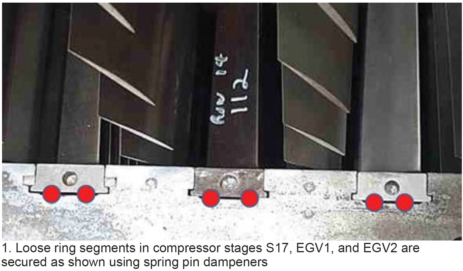
Compressor stator-vane looseness: What to look for and what to do
CTTS (a/k/a Core Tech)
Pinning is a relatively low-cost and quick solution for gas-turbine owner/operators challenged by compressor stator-vane looseness. More than 200 engines have been “pinned” in the last 20 years, avoiding engine damage and saving thousands of vanes (Fig 1).
The pinning technique, developed by Rodger Anderson, who began his career as a member of GE Frame 7 compressor design team, has been the subject of several CCJ articles over the years. What to look for during your next compressor inspection in terms of shim migration and vane looseness/damage is described in the slide deck along with the likely causes.
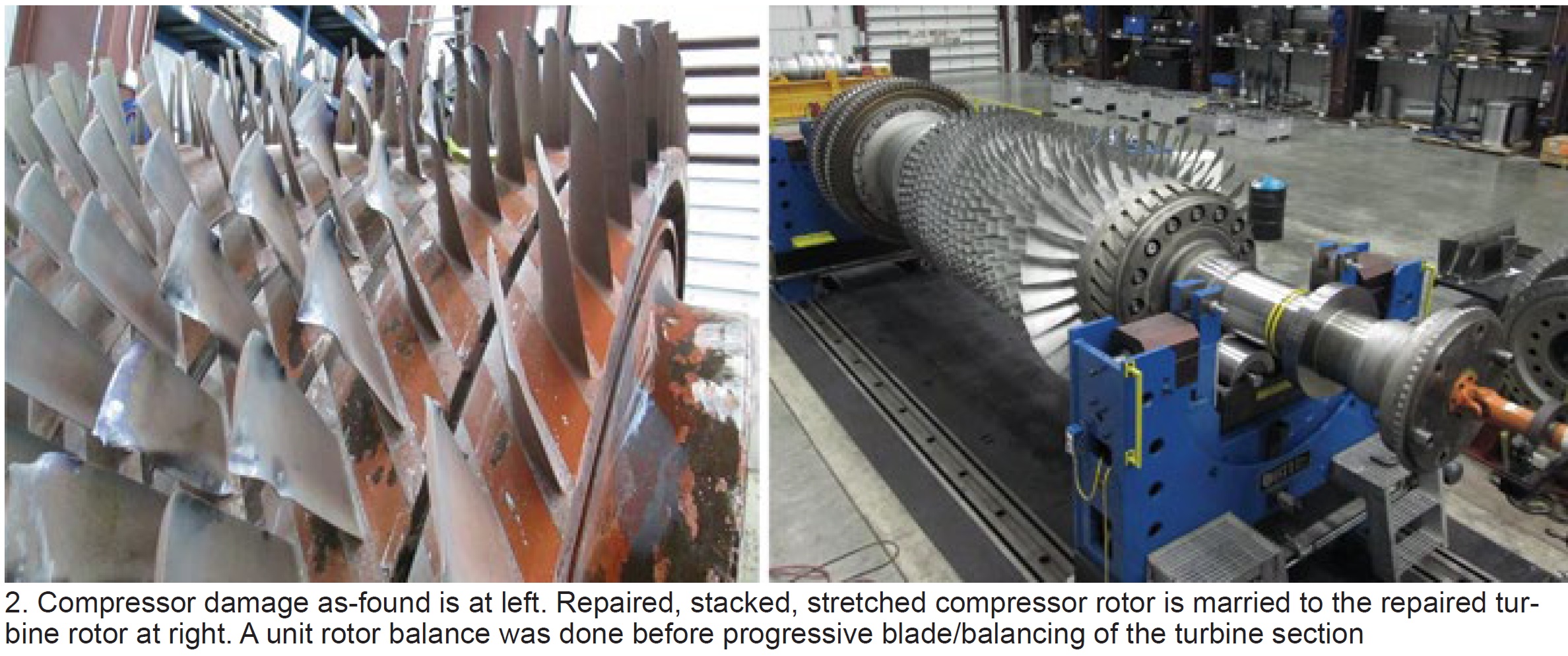
Emergency rotor support services—a case study
Sulzer
The borescope inspection of a simple-cycle 7F unit revealed severe damage in compressor rows 14 through the exit guide vanes (Fig 2 left). The owner/operator needed the unit back in service ASAP. Presentation slides detail the steps taken to assure proper corrective action—from inspection to rotor disassembly to parts replacement with shop-manufactured components to reassembly (Fig 2 right) to rotor balancing to preparation for shipment to the plant—in only 36 days.
Details presented in the slides provide a valuable learning experience for the plant team. The second part of the presentation gives details on Sulzer’s capabilities, repair history, shop capabilities, rotor life assessments, and field services.
Analysis of inspection protocols for S-1/R-1 clashing
Veracity Technology Solutions
The goal of an inspection protocol should be to provide the highest sensitivity for flaw detection and determine an inspection frequency that gives the inspector the most opportunities to detect a flaw before the defect becomes catastrophic.
In the example given, two units were undergoing their annual NDE inspections to satisfy the requirements of TIL-1884 (see first item above). The units were equipped with C450 stators, which exhibited signs of corrosion lockup in the lower half after nearly 11,000 fired hours and 2000 starts. An eddy-current inspection was specified; a fluorescent penetration inspection was conducted as well to validate the findings.
Many indications were identified and are shown in the slides. Analysis revealed the cracks emanated from shallow surface discontinuities which experts believe were caused by one or more of the following: environmental conditions, possible stress corrosion cracking, and high-cycle fatigue (from stator lockup in the vane carrier).
Conclusions: The use of traditional penetrant methods may not be effective for detecting the types of cracks found. Only after the stators were removed and sent to the shop did the inspection team identify all of the flaws using its proprietary inspection technique.
It’s important to note that swapping out of the Type-C403 stainless-steel stators installed on older machines with C450 components recommended by the OEM may not provide the level of asset protection desired. The bottom line: It’s imperative to be diligent on your inspection protocol.
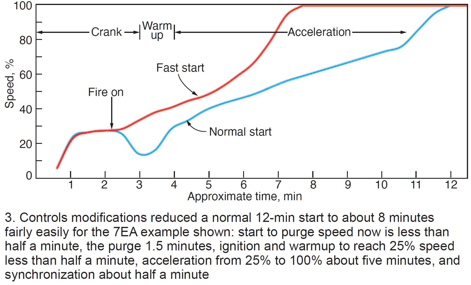
Getting your 7EA ready for increased run time
Emerson
If you’re looking for a checklist of action items to improve the run times of your units, reading through this presentation is a good place to start. It focuses on controls mods, generally far less costly than hardware changes, to consider. Example: Control mods can enable the transition from normal to fast starts (Fig 3).
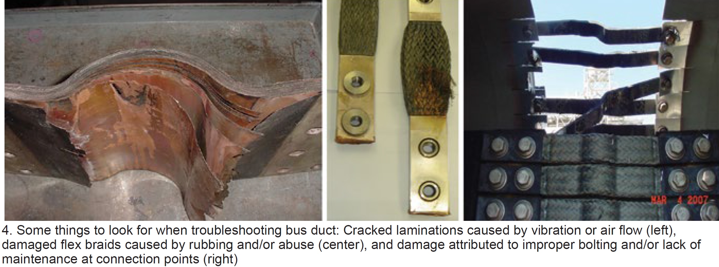
Bus maintenance in action
RMS Energy
Bus duct is relatively easy to maintain. Keep it dry, clean, and cool, the RMS Energy experts say, and your problems will be minimal. But how many plant personnel do you see walking around outside and looking up? And even if they were, the upper portion of the duct remains out of sight.
The presentation begins with a list of critical bus-duct components: Flex/bolted connections (current carrying), expansion bellows/joints, insulators and mountings, seal-off bushings, grounding, and insulated joints. Fig 4 shows some of the damage one can expect without a rigorous monitoring/inspection plan.
Monitoring equipment/techniques suggested include these: Thermocouples and infra-view camera to monitor components remotely and initiate alarms. Electromagnetic signature analysis (EMSA) is a valuable online diagnostic technology that can support maintenance decisions based on real-time operating conditions. It can save critical shutdown time by eliminating the need for offline testing.
Several case studies with before/after photos are instructive.
The GTC quick solutions package
GTC Control Solutions
Five case studies encompass this presentation; four are explained below.
The first describes a single point of failure. Problem: A high differential among ambient-temperature thermocouples (t/cs) was causing a “not ready to start” situation. There were two compounding issues: The first was sub-optimal location of the t/cs. This second: A “no high differential” was a start permissive—that is, a high differential would result in a “not ready to start” condition.
The fix: Two t/cs were relocated to prevent erroneous temperature measurements. Plus, the “no high differential logic” as a permissive to start was changed to “two out of three t/cs failed.” The latter assures that if one t/c fails, operators receive an alarm but will still remain ready to start; two failed t/cs interrupt the start sequence.
Case 2 involved an LM5000, which has two speed pick-ups per shaft. Originally, the “Hi-Select” determined speed. Thus, one failed hi-detector trips the unit. Solution was to check inputs and reject “out-of-limit” values.
Case 3 involved an LM2500 with very hot starts. Over-temperature trips occurred during startups. Diagnostic alarms indicated a loss of P2 pressure feedback. Solution was a logic change to “IF on temperature control during startup THEN trip.”
Case 4 described problems with a 7B gas turbine equipped with torque converter, jaw clutch, and limit switch that experienced starting difficulty. Clutch disengaged at 47% speed; however, logic required clutch to remain engaged until 50% speed. Torque converter degradation was the problem and the logic was changed to permit clutch disengagement below 50% speed.
Gas-turbine operability challenges in an unstable grid environment
EthosEnergy
Chris Chandler, chief technologist for turbine optimization, warned attendees that recent grid-wide reliability events in California (summer 2020 ) and Texas (calamitous winter freeze 2021) were likely to be experienced nationwide as the percentage of renewables on grids keeps growing. Because gas turbines and combined cycles will be expected to “pick up the megawatt slack” when renewables output drops by hundreds, and even thousands, of megawatts precipitously, combined cycles need to adapt for operation at the “lowest sustainable limit” (LSL).
Balance of Chandler’s presentation explains how the company’s Ecomax Extended Turndown optimization package can extend the life of the equipment while operating more hours at LSL. It addresses the consequences of operating at prolonged maximum turndown states, most importantly the inability of the HRSG to adequately attemperate and higher CO production from the combustor.
Operators are alerted in real time what the LSL is and the Ecomax Extended Turndown “knobs” are used to operate at that point until CO becomes an issue. The system can boost GT output by 5 to 15 MW per unit at the low end, says Chandler. As of this presentation last year, the concepts had been validated and the program was in commercial development with a lead user.
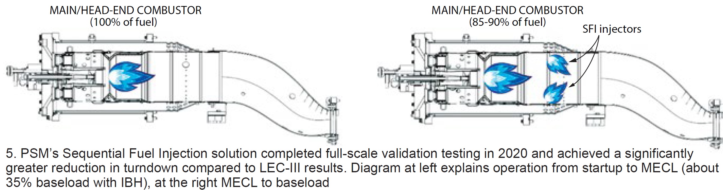
7EA turndown solutions: How low can we go?
PSM
Presentation is a good review of PSM’s tools for extending engine turndown. It begins with a review of the company’s LEC-III™ ultra-low emissions and LEC-NextGen combustion systems and refreshes your recollection of its inlet bleed heat and exhaust bleed solutions.
PSM’s latest turndown solution—Sequential Fuel Injection (SFI)—specifically engineered for 7E (that is, Models 7B through 7EA) LEC and DLN 1 combustion systems is the presentation’s focus. SFI is said to leverage prior sequential combustion experience with the company’s FlameSheet™ product, to achieve comparable results with SFI without major changes to existing combustion hardware (Fig 5).
Recall that low-emission combustors are sized for optimum NOx emissions at baseload and “lean-out” as load is reduced; CO spikes as the Minimum Emissions Compliant Load (MECL) is approached. With SFI, the main/head-end combustor is sized for CO at MECL, and SFI fuel is added proportionally as load is increased from MECL to baseload (up to 15% of the total).
SFI fuel reacts with hot excess air from the main/head-end combustor, holding the temperature rise in check, thereby minimizing NOx production while also maintaining low CO.
Remote operations for simple-cycle GT sites
Emerson
Lots of things to think about if your simple-cycle unit is not yet equipped for remote operation. Presentation’s stated goal is to help users leverage digital transformation to save O&M and increase earnings.
Using flow net modeling to optimize fuel-nozzle calibration and flow testing
Trinity Turbine Technology
New ideas for optimizing combustion-system air and gas mixing to reduce emissions and temperature spreads. Results have been promising; work continues.
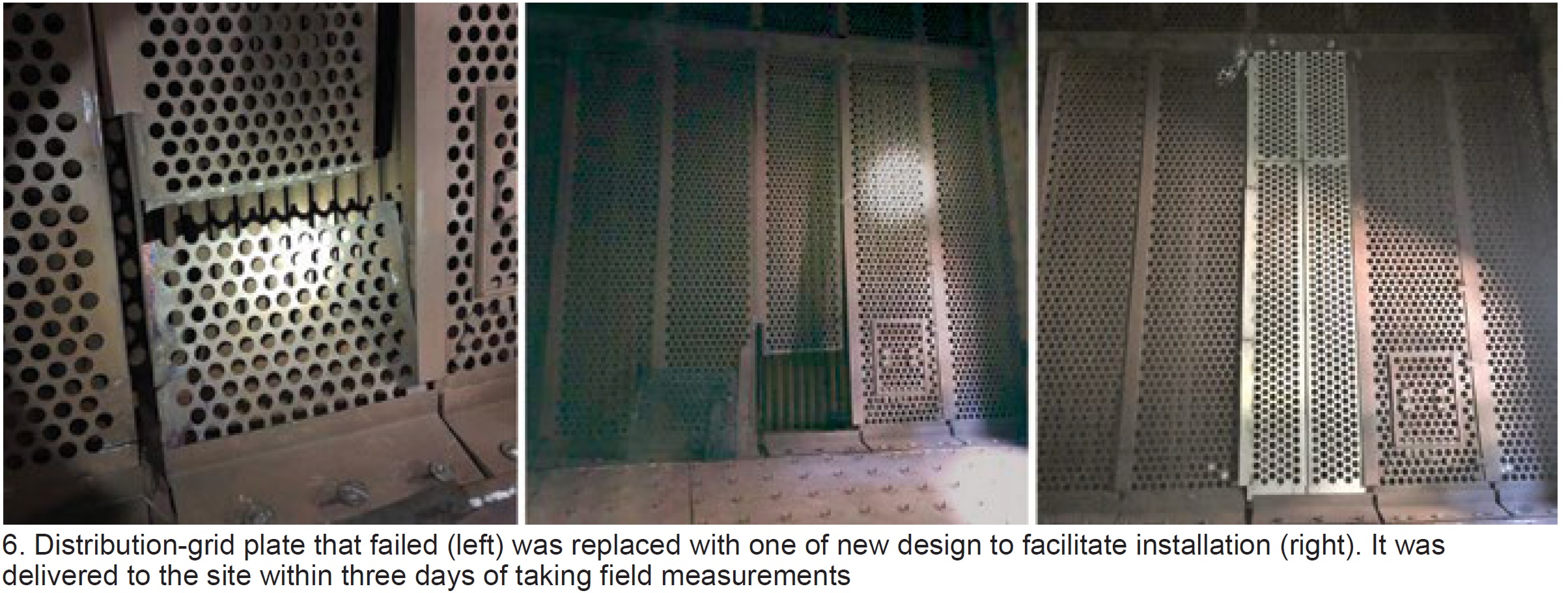
Emergency material and design support
Schock Manufacturing
Slide deck focuses on Schock Manufacturing’s ability to respond quickly to customer problems—such as expansion-joint blowout, exhaust-liner sheet failure, diverter damper seat and landing-bar failures, failed trash screens, stack corrosion, failure of silencer panels, etc (Fig 6). Customer testimonials are included.
Generator testing: What the tests mean and how they are resolved
AGT Services Inc
Jamie Clark had a simple objective here: Identify standard tests and inspections—electrical, mechanical, and visual—that plant personnel should be familiar with to avoid operational surprises and to assure the highest level of equipment reliability possible. He provided examples of both bad and good test results, and offered recommendations and corrective actions to achieve the stated objective.
Here’s the lineup of components Clark recommends inspecting:
- Stator winding: Endwinding support system, wedge system, gas-gap baffle studs, rubber baffles, and bushing box for hydrogen-cooled machines.
- Stator core: Tightness, iron migration, damaged/overheated laminations, and vent duct blockage.
- Field (rotor): Cleanliness, arcing between wedges, hot spots on tooth tip at wedge joints, retaining-ring condition, borescope look under retaining rings, collector-ring condition, fan damage, and copper dusting.
This is a good presentation for a lunch-and-learn in the plant break room. Details are at a minimum, photographs are excellent.
Considerations for the fleet management of gas-turbine lubricants
EPT Clean Oil
Company specializes in ion-exchange-based lubricant treatments and oil testing in critical applications. It maintains an on-going R&D program focused on advancing the science of lubricant management.
Peter Dufresne’s goal was to help owner/operators see the value in treating their lubricants as an asset, rather than as a consumable, and to understand and use the tools at their disposal to manage that asset. Here’s an “executive summary” of the plan he suggests users follow. Details are in the 49-slide PowerPoint.
- Complete oil analysis done to ASTM standards.
-
- Track and monitor rates of additive consumption.
- Predict end of lubricant life well in advance.
-
- Use a conditioning system to manage oxidation.
-
- Eliminate potential for varnish and reduce rates of additive consumption.
-
- Purchase high-quality oils from a reputable manufacturer/supplier.
-
- Consider an annual 5% top-up.
-
Lincoln, Crete earn Best Practices Awards
Peaking plants Lincoln Generating and Crete Energy Venture were the only facilities in the 7EA fleet recognized for their best practices in 2021 (details below). Interestingly, both are operated by Consolidated Asset Management Services LLC (CAMS) and managed by Brad Keaton, facilitating the sharing of best practices for maximum impact. Lincoln, located in Manhattan, Ill, has eight simple-cycle units, Crete, located in Crete, Ill, four.
Safety, reliability foremost when purchasing a mobile fall-protection system
Several locations at Lincoln Generating Facility and Crete Energy Venture required fall protection where no adequate tie-off points were available. One of the most notable: Generator circuit-breaker platforms at Lincoln (Figs 7 and 8). When performing generator breaker work from the platform, personnel had adequate fall protection. However, the work often required climbing up to a higher level, which exposed workers to a fall risk and therefore the need for fall-protection harnesses.
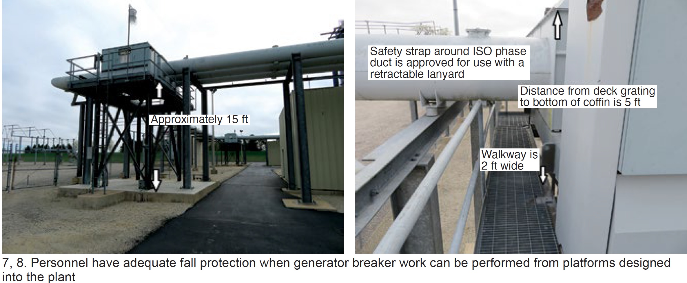 A problem arises when the technician is standing on the highest point in the area and is only able to tie off to the equipment that he/she is standing on. If the person were to fall to the platform below, the fall protection would not work, because the drop is less than the distance required to fully engage the fall-arrest lanyard, but it’s still high enough to cause serious injury.
If the technician fell off the structure entirely, the fall-arrest equipment would come into play; however, there is a possibility of injury by the fall-arrest system because of the distance the worker would drop before activation.
Lincoln staff explored numerous options over the years to eliminate the fall risk described—including temporary scaffolding during planned maintenance, which was not practical when required for unexpected issues forcing the unit into an outage. Permanently installed tie-off points proved costly because of their installation and periodic testing requirements.
Personnel observed a demonstration of an OSHA-approved mobile tie-off system, which could be used in many different locations at Lincoln, and shared with Crete (Figs 9 and 10). The system demonstrated had tie-off points for three workers. It received owner approval and an OSHA-approved system was purchased.
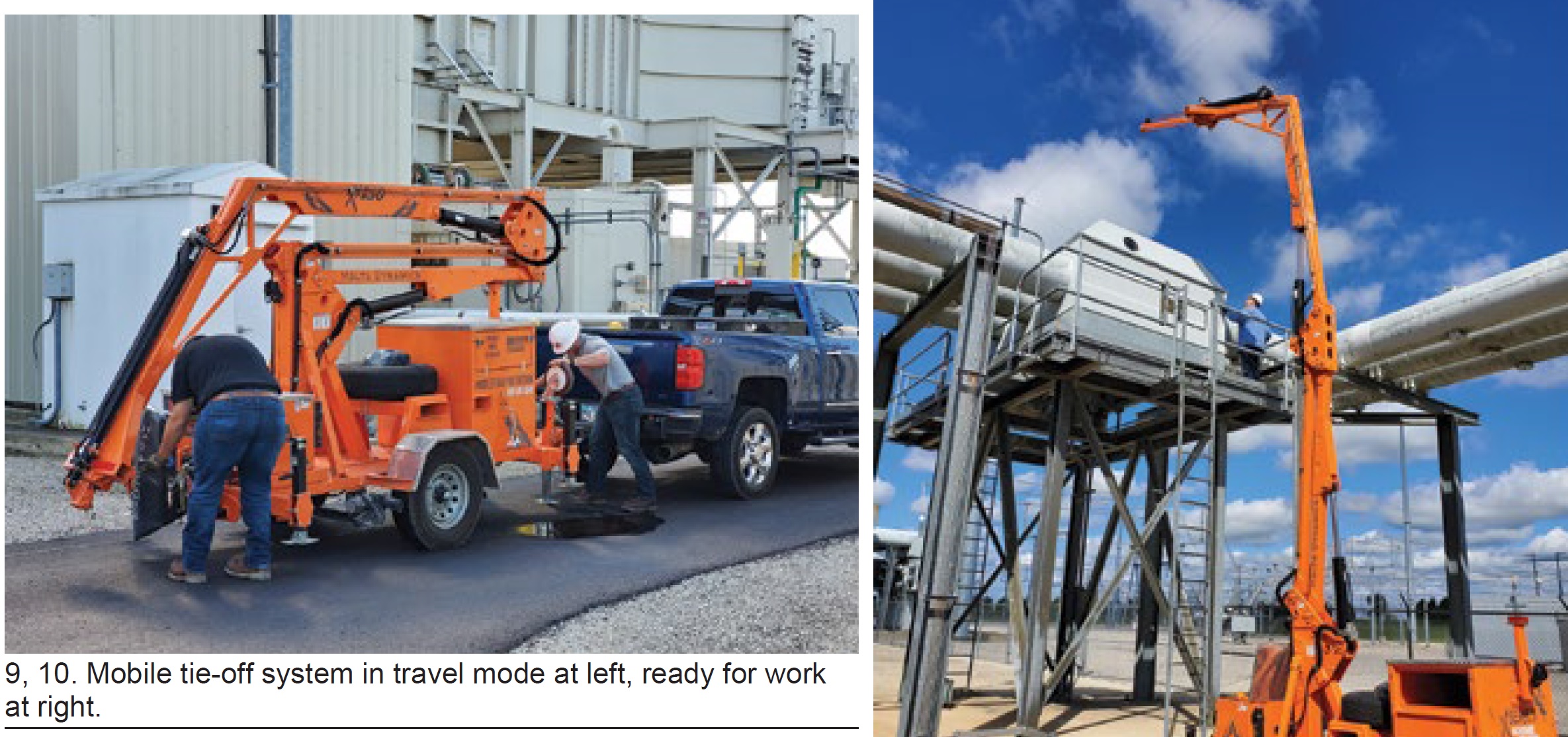
The mobile tie-off system has been used successfully in many locations at Lincoln and Crete. Its proven benefits include the following:
- Cost was half that for permanently installed systems considered for just the generator circuit-breaker platforms.
- The mobile system has tie-off points for three workers, which is adequate for the work scopes plant personnel perform.
- Scheduling and coordination of temporary scaffolding during outages is no longer required.
- Staff now is capable of safely performing emergency repairs.
Mark V lifecycle, reliability improvements produce dramatic results
Crete Energy Venture, commissioned two decades ago during the gas-turbine boom, was experiencing challenges with obsolescence, parts availability, and OEM support. This was especially true for the Mark V gas-turbine control system. OEM declarations ceasing production support of system components in 2014, outdated HMI interfaces and hardware, limited OEM training offerings, plus the wear and tear of daily operation, led staff to investigate methods for the continued reliable operation of the control system.
After performing their due diligence, it became clear to plant management that a full control-system upgrade was not necessary, as multiple third-party vendors provide solutions for parts repair/replacement and field service support, and the functionality of the TMR (triple modular redundant) Mark V controls remained robust. Staff determined that multiple methods of improvement were available for a comprehensive control-system reliability program and implemented the following solutions:
Mark V health checks. Since 2016, Crete has hired a third-party vendor on a biennial interval to perform reliability assessments of the Mark V control panels and associated equipment. It identified numerous issues lingering below the surface which eventually could have caused forced outages if not addressed.
Mark V cards, ribbon cables, and instruments have been replaced proactively during the assessments, and bad wiring terminations in remote junction boxes have been corrected. The permanent clearing of what could be considered nuisance Mark V diagnostic process alarms and dc-equipment grounding issues also was a site priority during the process. Result: The plant now experiences significantly fewer unplanned equipment failures than previously.
Inventory management. After the initial increase in site inventory and the addition of firmware revision-specific spares—such as EEPROMs (electrically erasable programmable read-only memory)—plant personnel continued to discuss optimized plant inventory levels for each Mark V card and component during every reliability assessment.
Increased inventory levels of high-use/high-failure-rate boards, like the TCEA and TCPS, have proved beneficial on multiple occasions, reducing downtime during controls-related upsets. Crete also replaced the GE TCPS power-supply boards with an upgraded aftermarket version from GTC Control Solutions after experiencing a failure or alarm condition that predicted future issues. Any used card, or one of unknown condition, that may have been replaced during troubleshooting also is sent to an outside vendor for a condition assessment and in-panel test to ensure that all site inventory is functional upon installation.
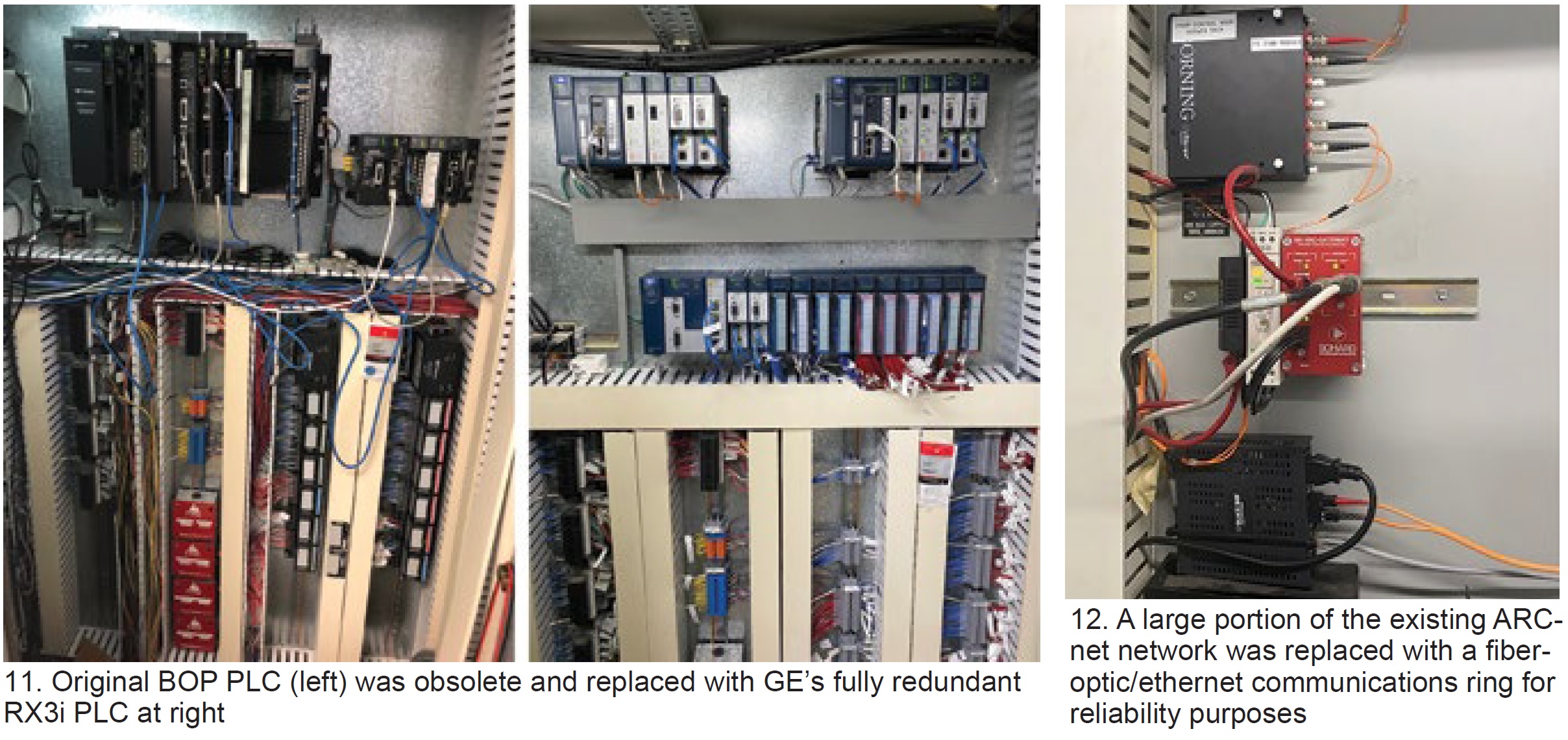
BOP PLC upgrade. The original installation used an obsolete pairing of GE Fanuc 90-70 and 90-30 PLCs—each with limited parts availability, single CPUs, and the need for a no-longer-supported Genius Bus Module communications device (Fig 11 left). Personnel determined that because of obsolescence, single-point-failure risk, and limited forward compatibility, this PLC should be replaced. The latest product offering from GE was selected and a fully redundant RX3i PLC was installed by Innovative Werks in fall 2019 (Fig 11 right).
HMI upgrade. The site’s OEM Cimplicity HMI servers were a major point of concern when assessing overall reliability, cybersecurity, and functionality of the turbine control system. Continued hardware issues required extensive man-hours for monthly server backups and re-boots to prevent server and ARCnet lockups. Plus, the Windows XP platform had long been obsolete, increasing cybersecurity vulnerability.
Additionally, the existing system had only one Mark V server in the control room and one in Unit 2’s packaged electrical and electronics control center (PEECC), limiting access to logic forcing, signal name, and TC2K reports, as well as to more advanced Mark V engineering and diagnostic tools.
Crete contacted TTS Energy Services to install a redundant server TMOS HMI system in May 2020. The Traffic Management Operating System eliminated a large portion of the existing ARCnet network and replaced it with a fiberoptic/ethernet communications ring, removing a costly and long-lead-time failure point from the control network (Fig 12). Recall that Cimplicity HMI ARCnet cards are proprietary and difficult to source.
This system also did not require any modification or head-end upgrades to the Mark V control panels, making it a very cost-effective solution. The new network topology includes a client HMI workstation in each of the plant’s four PEECCs and the control room, giving technicians full access to the Mark V control screens and engineering tools in all locations.
Easier access to dynamic point logic, trends, and signal names/values directly from the control screen provides a more intuitive operator interface, allowing for reduced troubleshooting time during abnormal plant operating events and a more simplistic training process. It also provided the site with state-of-the-art Windows Server 2019 and Windows 10 operating systems. Continued patching and Windows support for these machines allow Crete to maintain a high cybersecurity standard on the controls network.
While each of the aforementioned projects individually would have had a positive impact on the lifecycle of the existing Mark V controls system, Crete has seen marked improvements in hardware reliability and system functionality after implementing the full program. Mark V card replacements, when required, typically are done proactively, rather than reactively.
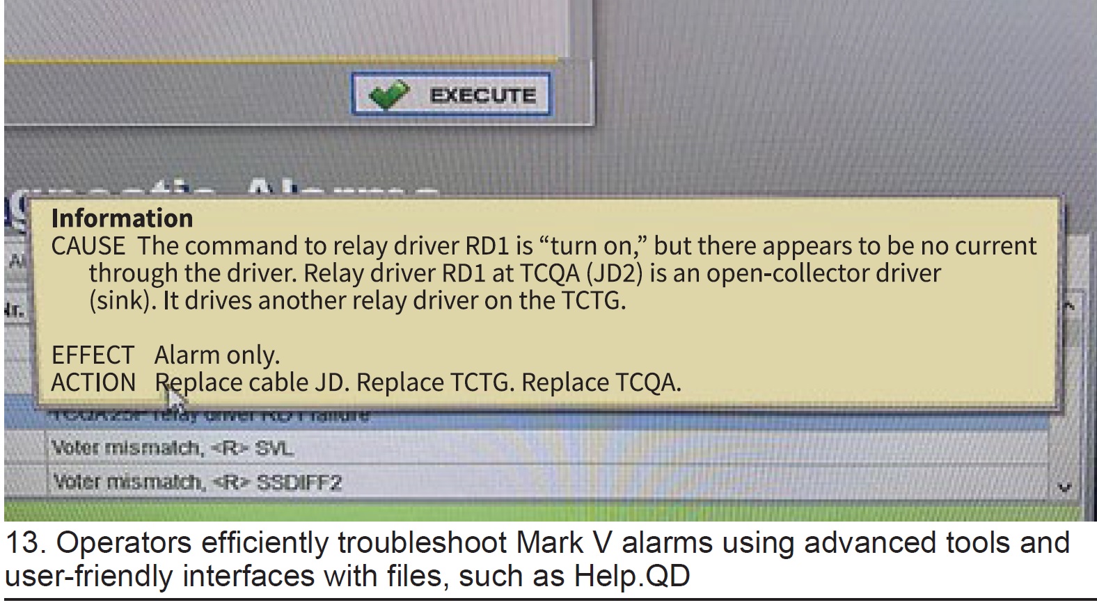
Operators are able to efficiently troubleshoot Mark V alarms using advanced tools and user-friendly interfaces with files such as Help.QD (Fig 13) and direct click access to dynamic logic rungs. Technicians learning Mark V can be trained on specific tasks with ease, removing the tedious and time-intensive process of learning and perfecting the exact syntax and terminology used in command prompt.
Additionally, the TMOS came quipped with a historian, giving personnel access to higher-resolution operating data without requiring a View 2 file to be running to capture operating events.
With the process improvements described, and with resources in place, site personnel are confident they can continue reliable and sustainable operations with the Mark V control system for many years to come.
LED lighting upgrades make for safer maintenance, operation
With a staff of three, the Crete site continuously explores methods for optimizing maintenance activities and eliminating high-man-hour tasks that don’t directly contribute to the site’s high standard for safety, reliability, and availability. While evaluating the facility’s equipment condition and the man-hour contribution of different systems, staff determined that a significant amount of time was being spent on changing MCC indicator lights and fluorescent building lights. Plus, a man-lift rental was required annually for street-lamp replacement.
Constant lighting failures also presented a safety concern, because failed indicator-lamp sockets can cause confusion on equipment operating status. Plus, plus, ergonomic constraints for replacing other fixtures increased hazard exposure. Considering these issues, as well as the potential to improve energy cost efficiency and reduce hazardous waste generation, plant personnel pursued an alternative, and simple, solution.
Advances in LED lighting technology afford industrial facilities the opportunity to upgrade lighting cost-effectively. Plant personnel researched product offerings and found solutions for the majority of the site’s lighting fixtures. Outdoor high-intensity-discharge (HID) lamps were replaced with LED equivalents expected to reach more than 94,500 hours of useful life with vastly improved light dispersion and output.
MCC indicator lights and sockets in the PEECCs were replaced with relampable LED fixtures that have a much brighter display and required no modifications to wiring or bucket mounting. The control building, switchgear building, PEECCs, generator breaker cabinets, and accessory gears all were retrofitted with LED lighting solutions over the last three years.
Today, the only remaining non-LED lights onsite are the turbine-compartment and fuel-gas-module lamps because there are relatively few product offerings that can withstand the operating conditions and/or regulatory requirements for hazardous atmospheres.
After the lighting upgrades, the man-hours required to replace failed lighting has been reduced from about 200 hours annually to fewer than 20. Hazardous waste generation related to lighting (as well as universal waste from ballasts) has virtually been eliminated because all remaining non-LED fixtures are incandescent bulbs. The improvements to site safety also are notable, as better work-area lighting and reduced hazard exposure are in line with Crete’s commitment to employee safety and continuous process improvement.
Gas turbine systems produce over one-third of US electric energy requirements. They provide reliable baseload power, in addition to that required to support the intermittent production of electricity from renewable sources. According to a recent Washington Post article, “Turns Out Wind and Solar have a Secret Friend: Natural Gas,” every 0.88% of capacity from renewables needs 1% capacity back-up from a fast-reacting fossil-fuel system.
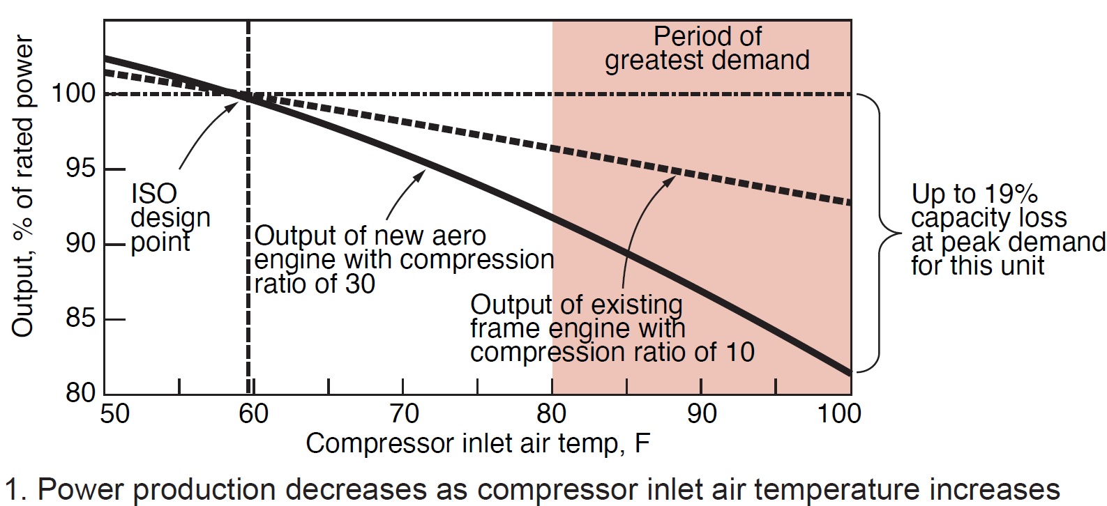
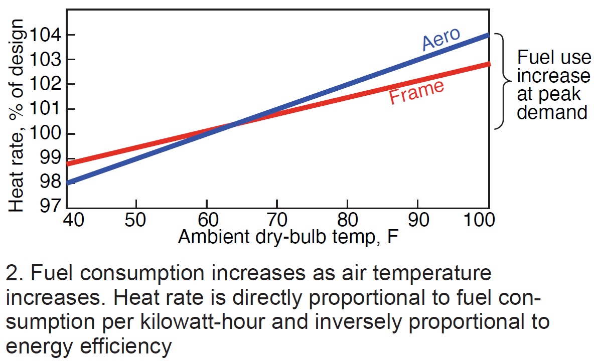
Thus, gas turbines, a cornerstone energy conversion technology for the efficient production of electricity and heat today, are destined to play an important role in the emerging global quest for zero carbon emissions, says Dharam Punwani, executive director, Turbine Inlet Cooling Assn (TICA).
He reminds that increases in ambient temperature and humidity adversely affect the output and energy efficiency of all gas turbines (Figs 1 and 2). Since high ambient temperatures reduce gas-turbine performance, the logical solution for preventing this adverse effect is to cool the inlet air before it enters the compressor. Several technologies have been used successfully for this purpose.
The Turbine Inlet Cooling Assn’s (TICA) website at https://turbineinletcooling.org is an excellent source of information on these solutions, especially recorded webinars bulleted here:
- Adiabatic wetted media evaporative cooling
- Fogging for evaporative cooling
- Wet compression
- Indirect heat exchange with chilled water
- Thermal energy storage for chilled water indirect heat exchange
- Hybrid cooling
The website also includes an inlet-cooling performance calculator, database of installations, and library of publications and presentations on all technologies.
Bear in mind that each technology has its pros and cons. No one technology is best suited for all applications. Selection of the optimum technology for your plant depends on many factors—including gas-turbine design, weather data for the plant location, value of additional electrical energy produced, and the value of unitized fuel saving.
The following summarizes the benefits attributed to cooling of gas-turbine inlet air:
- Increased power output.
- Increased energy efficiency.
- Reduced emissions per unit of electric energy produced (higher efficiency).
- Reduced grid-wide emissions (reduced need to operate less-efficient systems for meeting grid demand).
- Increased thermal energy in exhaust gases, which benefits combined-cycle and cogeneration systems.
- Lower capital cost compared to the addition of a peaking unit to increase capacity.
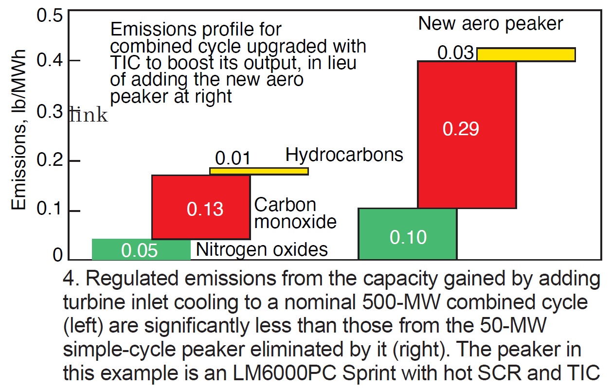
Because combined cycles are the most efficient fuel-fired option for producing electricity, upgrading with inlet cooling eliminates the need to operate a less-desirable alternative—such as running a simple-cycle peaking turbine with a rated capacity equal to the combined-cycle output gained by adding inlet cooling.

Examples of the quantitative benefits of using TIC on a 500-MW combined-cycle system for reducing emissions of carbon dioxide and regulated pollutants, are compared in Figs 3 and 4 to the emissions from a simple-cycle peaking turbine whose need was eliminated.
Similarly, installing inlet cooling on simple-cycle turbines eliminates the need to operate less-efficient systems.
According to an estimate by TICA, the use of inlet cooling on all combined-cycle systems in the top 20 states can reduce carbon emissions by more than 22 million tons annually.
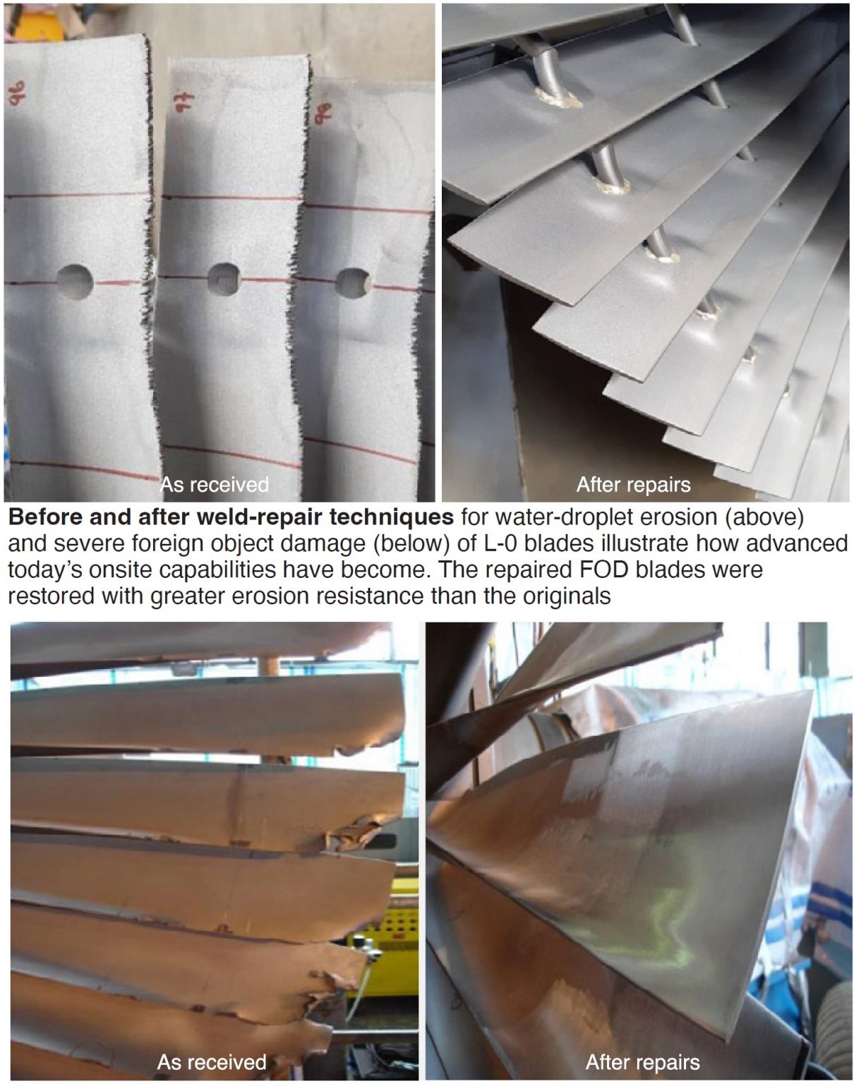
Sometimes it’s best to start at the end. During Ethos Energy’s October webinar, “L-0 Blade Repairs,” Ian Saeger, manager of project engineering, concluded by stressing that last-stage steam-turbine blade repair is usually at least 50% less expensive than blade replacement and accomplished within a few weeks—if the repair can be done onsite or in-situ. The latter means with blades still attached to the rotor, the former when the blades are removed but still onsite. If blades have to be shipped to a shop, count on adding up to six months in the schedule.
Saeger began by polling the audience on primary causes of their L-0 blade replacements. Not surprisingly, 69% responded erosion, 10% root cracking, and 21% other. He then reviewed three repair case studies involving (1) water-droplet erosion, (2) cover cracking, and (3) severe foreign-object damage (Fig).
During the Q&A, Saeger noted that most blades with a stainless-steel base can be weld-repaired. Titanium blades, on the other hand, can be welded but only in a shop vacuum furnace. However, not all blade damage is repairable. Damage near the tips generally is amenable to weld repair; damage at the base of the airfoil typically requires blade replacement.
Another useful nugget: In-situ repairs don’t generally require high-speed balancing afterwards, if done within Ethos’ specifications and airfoil geometry remains the same. When asked if there is a limit to how often a blade could be repaired, Saeger said he wasn’t aware of any limit on the frequency.
Saeger’s last slide went beyond the topic and identified solutions for D11 and A10 steam turbine/generators specifically—including the following:
- L-0 blade erosion and root cracking (see GE Technical Information Letter 1795)—40-in. L-0 root and airfoil modification. Note that the company’s repair for root cracking caused by low-cycle fatigue is a proprietary upgrade.
- N2-packing casing cracks/leakage (see GE TILs-1627-R2 and -1749)—redesigned N2 box.
- Outer-casing joint leaks—machining of outer casing joint and hardware upgrade.
- HP/IP rotor vibration/runout/bowing—rotor straightening.
- Repetitive seal failures—EEG’s Smart™ Seals.
- Diaphragm axial distortion (see GE TIL-1589)—diaphragm trailing-edge and stiffening mod.
Users (approval required) can access this recording by registering at the following link:
https://attendee.gotowebinar.com/register/8437130390099617037?source=ccj
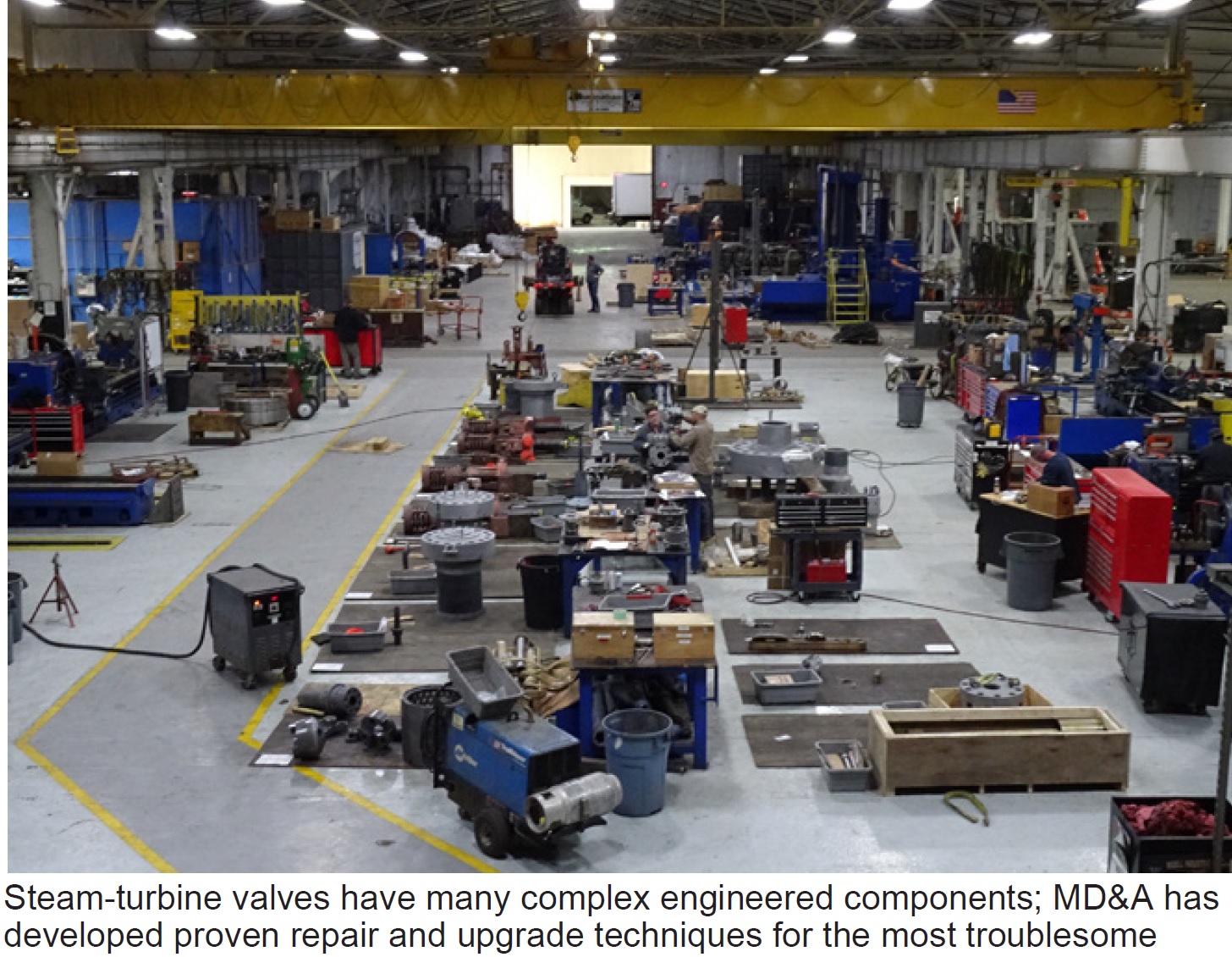
It only takes 2-3% steam overflow to trigger a steam turbine/generator (ST/G) overspeed event, cautioned Dean Casey, project manager for machining services at MD&A, to stress the importance of main-steam-valve inspections and timely repairs. During his presentation in MD&A’s fall series of webinars, “Steam Turbine Valve Outage Common Issues,” Casey went on to say that the failure of the main-steam stop valve to close is the most frequent cause of ST/G overspeed events.
Casey then led his audience through the often-arcane repair process details associated with these complex engineered components.
If you have main-steam valves approaching three to five years, or 25,000 hours, of operation, MD&A’s minimum recommendation for inspection and repair, you owe it to yourself to listen to the webinar. This is especially true if you are past the first five years of plant operations, when valve issues begin to rise. There are no industry or independent maintenance practices for these valves, outside of nuclear plants, only OEM guidelines, making webinars like this one even more valuable.
Generally, inspection and repair are targeted at: restoring clearances to OEM specs, such as bushing removal and replacement, hardened inserts, and scale removal; achieving concentricity, so that the valve operates precisely on its centerline; sealing and resurfacing to ensure no steam cutting; and attending to foreign object barriers, such as strainer baskets.
More specific topics and case studies Casey addressed include these:
- A bent stem which had to be replaced, along with the valve-stem bushings, and inserted into a re-machined casing fit.
- Solid particle erosion (SPE), which can cut stem life in half if not addressed. MD&A has developed a laser-cladding process for some valve stems. Seats, discs, and pressure seal heads are also affected by SPE.
- Control-valve seat replacement. Casey noted that MD&A has replaced 40-50 of these seats in one OEM’s valves over the last 10 years.
- Strainer basket replacement.
- Specific repairs for spindles and sleeves in Alstom valves, and disbonding and liberation of Stellite hardfacing of Siemens KN valve seats and plugs.
- Indications (cracks, for example) in steam chests and repair options.
With supply-chain issues affecting short-term delivery to all sites, Casey urged users to identify parts for rebuilds well ahead of the outage. Around 90% of MD&A’s parts come through its Parts Div facility in Danvers, Mass, but some can be manufactured in its St. Louis shop, which Casey described as the largest non-OEM gas-turbine repair shop in the US. Examples of the latter include non-hardened bushings, inserts, and sleeves.
Capabilities in the St. Louis shop include (1) a deep-bore TIG (tungsten inert gas) welding machine designed to handle internal diameters from 4 to 30 in. and depths to 50 in.; (2) automated MIG (metal inert gas) welder for IDs from 0.88 to 27 in.; and (3) an induction machine for uniform temperature during post-weld heat treatment.
Access this recording @ https://www.mdaturbines.com/webinar-archive/
MD&A kicked off its fall 2022 webinar series with a presentation on rotor life extension. You’ll want to take an hour and listen in if your plant has a 7F unit approaching 5000 starts/144,000 equivalent operating hours (EOH) or a 7B through 7EA unit approaching 5000 starts/200,000 EOH. Get the background on these requirements in “Heavy-Duty Gas Turbine Operating and Maintenance Considerations,” GER 3620P, January 2021, available at no cost on the Internet.
Fred Willett explained that MD&A seeks a balance between a standard approach and one customized to address each user’s unique machine characteristics. “All new rotors are the same, but all used rotors are unique,” he said. For this reason, Willett had to answer most of the questions with “talk to our sales rep”—questions such as “What is the lead time for a 7FA rotor?” and “Can you do compressor reblading at the customer site?”
Goal of a rotor lifetime assessment (RLA) is to designate each rotor component for reuse, repair, or replace “for the continued safe and productive operation of the unit” (Fig). For example, thermal transients impact the back-end stages of a compressor far more than the early stages. In one example, Willett noted that new wheels were required for Stages 13-17 while Stages 1-12 could be repaired or reused.
Temperature obviously is the main factor in the stress concentrations in latter stage wheels but Willett also dwelled on the contribution from the “dovetail skew angle” which increases from the front-to-back stages of the compressor discs.
Regarding the turbine section, Willett noted that disks “have had their share of problems,” and in recent years, so too failures of the 1-2 spacer, for which “there is more than one machine failure known.” Importantly, MD&A offers first-stage discs with redesigned cooling slots, has patented a geometry for an upgraded 1-2 spacer, and has upgraded components for all the other rotor problem areas.
Willett touted MD&A’s parent, MHI, and, as an OEM, its “deep domain expertise” in this area. MHI has conducted over 270 comprehensive rotor inspections, with shops and labs in the US and Japan. Some of that expertise was obtained by reverse engineering and manufacturing rotors which were purchased by customers but never installed or operated. When one listener asked if MD&A’s upgraded components also have durability improvements, compared to the OEM, Willett’s answer was an unequivocal “Yes.”
The slides include some very insightful heat maps of compressor rotors during different points along the startup and shutdown sequence, as well as detailed diagrams of component stress concentration points.
Access this recording @ https://www.mdaturbines.com/webinar-archive/
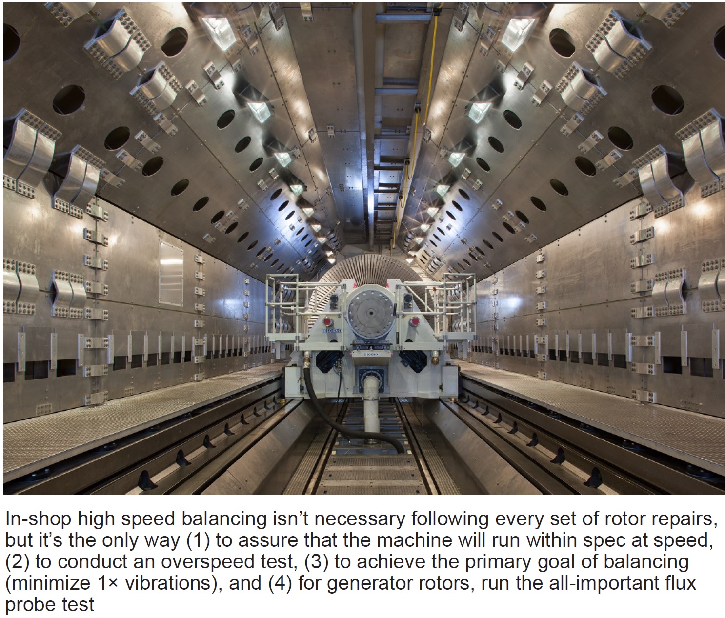
The underlying message of MD&A’s third webinar in its fall 2022 series is that a shop which has invested in a high-speed rotor balancing (HSB) machine (photo) offers the user clear advantages in shortening outage schedules and avoiding the risk of having to transfer the machine from the shop where repairs are made to a shop with an HSB.
Not all rotors require HSB after being repaired, noted MD&A’s Keith Collins, in his presentation entitled, “High-Speed Balance.” If repairs are minor, a low-speed balance (LSB) will suffice, or even an onsite balance. But if the rotor has undergone journal machining, heat straightening, or weld repairs, as a few examples, you should opt for HSB. Ditto if any repairs have altered rotor geometry or local stresses.
For a generator rotor, the big advantage of HSB is the ability to perform a flux probe test, the “only way to guarantee no shorts at startup,” said Collins. Turn-to-turn testing in the shop cannot detect speed-sensitive shorts. “If the rings come off your generator rotor you should do a HSB. This is true for a rings-off inspection or a rewind with new or existing copper,” he stressed.
For all rotors, the HSB also allows for overspeed test and comprehensive vibration analysis.
The bulk of Collins’ slides offer a tutorial of sorts on topics including applicable standards, vibration measurement basics, critical speeds, modal balancing, overspeed test and balance, electrical testing, and heat and stability runs.
During the Q&A, Collins added that an onsite balance should definitely follow an in-shop HSB, with experts present to determine need for additional trim shots. On the subject of whether MD&A “heats up the GT/G or ST/G rotor in the shop for HSB, Collins replied that they typically do not, though other shops do. “We can draw partial vacuum to heat up the blades which transfers heat to the rotor for soaking,” he said.
Regarding the question, “Should you do an onsite LSB after a partial re-blade,” Collins replied “Yes. Do an LSB before and after the repairs.” To a similar question of doing an LSB after replacing all blades in an ST/G rotor, Collins also replied “Yes.”
Access this recording @ https://www.mdaturbines.com/webinar-archive/