Recognized for Best Practices in Environmental Management and Safety
 Design hazardous-spill response plan for worst-case scenario
Nearly all plants have a plan for addressing hazardous spills. Many, like 801-MW Green Country Energy (GCE), owned by J-Power USA and operated by NAES Corp, have a comprehensive spill-prevention control and countermeasures plan that identifies areas where spills could happen, as well as appropriate responses to them. The challenge is to develop a plan which takes into account the location, weather, and staffing conditions that would be present at the time of a spill event.
A successful plan is one that can easily and quickly be executed by anyone at the facility. It should require very few steps to complete and ensure the safety of those involved. Plus, it should deal effectively with any spill—small or large.
At GCE, personnel have worked to improve the plant’s plan so it meets all the criteria mentioned above. In the process, however, staff began to identify obstacles fundamental to the success of other engineering necessities.
To illustrate: A modern, well-designed facility typically would engage with civil engineers to design flow paths and drainage channels that direct rainwater quickly to storm-water drains to prevent site flooding during heavy-rain events. But many facility drainage systems take rainwater quickly to underground piping systems, never to be seen again onsite. These well-designed and engineered systems actively work against the ability to properly manage a spill. Site spill plans must take this into account.
At GCE, any spilled material would enter the storm-water system swiftly, leaving very little time to contain the spill. During a major rain event, that time would be reduced even more. Staff, led by Plant Manager Danny Parish, assumed that storm water would be present during a spill and incorporated that into the plant’s control plan.
Another thing considered in creating a sound spill plan was the design of containments and containment drains. At GCE, transformer containments all have administratively controlled drain valves. Following a rain event, operations personnel visually inspect the water in the containments to ensure there is no oil or other contaminants. They then open the drain valve, which allows rainwater to flow to the oily water separator.
Some sites—not GCE—have position-indicating valves (PIVs) for these drains that visually indicate whether the valve is closed or not. It is critical to keep containment drains closed during normal operations so that, in the event of a spill, the containment can do its job. The lack of position indicators on underground containment drain valves at GCE created an opportunity for an administrative error. Thus, the plant’s plan required continuously visible indication on these valves so the operations team could ensure that they stayed closed at all times.

Another major consideration for GTC was that, during evenings and weekends, only three employees man the entire 20-acre site, home to three 1 × 1 F-class combined cycles. One stays in the control room, and the other two split their time between equipment rounds, readings, small maintenance projects, and other operations duties. This dictated that the plant’s spill plan be easily and safely executable by no more than two employees.
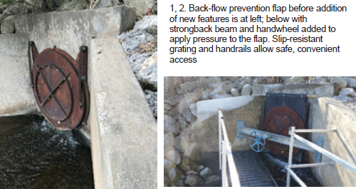
 Spill containment solution: GCE has a back-flow preventer at the Arkansas River discharge location that provides an isolation point for all of the water flowing from the plant (Fig 1). The challenge was to find a simple, cost-effective means of installing a positive closing device at this point. Staff decided on an I-beam strongback with a modified handwheel designed to put positive closure pressure on the back-flow flap. Technicians designed and engineered this device using scrap material and parts from an old valve.
The largest expense was the rubber sealing material placed between the cast-iron flap and the 48-in. pipe lip. To ensure that any employee could close this valve, a platform with a slip-resistant grating and handrails were installed to allow safe access in any weather (Fig 2).
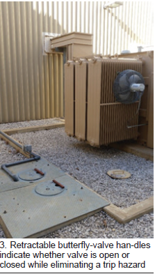
The drain-valve indicator issue was addressed by replacing all gate valves with one-quarter-turn butterfly valves. Extension handles then were fabricated to assure quick, easy valve operation. The handles are retractable to eliminate any trip hazard (Fig 3). The positions of the valves now can be seen at all times, allowing the operations group to ensure all drains are opened only during rainwater draining events.
Plant continues to use floor-drain covers, absorbents, dikes, dams, and diversions to mitigate small spills—but only after the back-flow flap has been closed.
How to excavate safely in high-risk areas
Safety is a core value at Green Country Energy (GCE) and identifying opportunities for safety improvement projects is a big part of what staff does on a daily basis. Many of these are simple to execute. Some take a little more time and planning; occasionally personnel face a safety-improvement opportunity that seems impossible to implement. Such was the case with installing protective bollards around the plant’s natural-gas supply.
Staff identified the need for bollards early on because the gas line is located at the plant entrance. Delivery trucks pass within 10 to 15 ft of it, and vendors, contractors, and other visitors pull into the administrative parking areas and then back up next to the line. The odds of someone hitting it are not great, but if they did, it could be catastrophic.
Plant personnel collaborated on a design. The bollards would consist of 8-ft lengths of 6-in.-diam steel pipe set vertically in the ground to a depth of 3 ft, then filled with concrete and painted bright yellow. If a truck or other vehicle were to make a navigational error near the gas line, the bollards would both protect it and minimize negative consequences to personnel and equipment.
The plant has many similar bollards to protect other equipment—such as the bulk hydrogen storage tank and fire hydrants. Most of these were installed during construction, some were added later.
Locating the bollards was complicated. A review of underground drawings showed the gas line came out of the ground right next to the plant’s gas chromatograph. Also, a storm-water drain was located just east of the line and a series of conduit runs were just to the north for conveying gas flow-meter and chromatograph data to the control room.
In addition, the bulk hydrogen line to the generators was routed through that area. Then there was the plant ring road alongside the gas line. If the bollards were moved far enough away from the gas line to clear all of these obstacles, they could pose more of a hazard to plant mobile equipment and personnel than the gas line itself.
The risks associated with any sort of conventional excavation appeared to outweigh the safety value of the bollards. Hand-digging in this area looked all but impossible because of the hard clay and rock. Result: The project was considered too risky to undertake and was put on hold for several years.
In 2017, plant management recommitted to installing the safety bollards around the gas line. After researching possible workarounds, a hydrovac services company was engaged to excavate the foundation holes. It relies on high-pressure water to loosen the soil, rock, and clay while simultaneously using a vacuum pipe to pull the loosened material out of the hole. This approach was effective and did not damage any underground cable, conduit, concrete, piping, or other critical equipment encountered (Fig 4). Excavation was fast, safe, and cost-effective, and GCE now has a fully protected gas line (Fig 5).

But unexpected things have a way of turning up when excavating in an industrial setting. This project was no exception. When digging the final bollard hole in a location that had no known obstacles, a buried pipe was found. It turned out to be the control-room sewage lift station line and was not on any of the drawings. Hydrovac spared the plant a messy and expensive outcome, reinforcing staff awareness that all excavations involve risk.


