
Low-cost thermal imaging camera assists Orange Cogen’s operators during rounds
Orange Cogeneration, a 2 × 1 LM6000-powered combined cycle owned by Northern Star Generation and operated by Consolidated Asset Management Services LLC (CAMS), exports power to the local utility and sells steam from its condensing/extraction steam turbine to an orange-juice plant and an ethanol plant across the street for process use. Plant reliability is of critical importance.
Like many plants today, the Bartow (Fla) facility owns a thermal camera for use by technicians in troubleshooting and inspecting various mechanical and electrical issues that present symptoms as thermal gradients. These cameras are precise and can measure very high temperatures, but they are also expensive and cannot be treated roughly by inexperienced or less-than-fully-trained users.
Plant Manager Allen Czerkiewicz’s team found a small plug-in thermal camera, made by FLIR® Systems Inc, that does not have the full capabilities of the company’s more sophisticated models but offers a wide usable range of detection and is relatively inexpensive (photos).

Although designed for attachment to a smart phone, Orange Cogen’s CAMS staff has mated it to an Android tablet which allows a very large display. Also incorporated into the plant’s assembly is a rugged tablet case that has a built-in strap allowing secure one-handed operation. The complete setup cost less than $650, allowing the purchase of multiple devices to outfit the operations staff.
Using the camera on normal rounds, operators have found hot spots in the HRSG outer casings, motor bearings that have begun to get hotter than expected, as well as electrical contacts that have become hotter than neighboring phases because of higher electrical resistance. This device also allows the easy capture and sharing of pictures of these identified issues so that follow up with the more advanced unit, if required, can be quickly made.
Best of all, although the thermal imaging system appears to be rugged and the plant has not encountered any issues in operation, management is comfortable knowing that if the unit gets damaged, it will not be too significant a financial burden if replacement is required.
Having this preventive-maintenance tool handy for the operations staff allows personnel to get ahead of any issues that show themselves through thermal variances and gives an improved predictive approach to Orange Cogen’s maintenance activities.
Continuous blowdown realignment at Channel Islands Cogen saves water, chemicals
The Channel Islands Power Cogeneration Facility, a 30-MW 1 × 1 combined cycle in Camarillo, Calif, operated for 30 years under a baseload power purchase agreement with the local utility. In April 2018, owner California State University began operating under a dispatch-style PPA.
The change in operating profile required the NAES Corp O&M staff to keep the HP and IP drums warm to meet startup times specified in the new PPA. Heat is provided by a sparging system which injects steam at the bottom of the steam-drum risers, thereby developing a natural-circulation pattern to sustain chemical mixing. The use of sparging steam increases drum water levels over time. Operators managed drum levels by venting steam from the tops of the drums and by opening the bottom drains when necessary.
The process of adding and draining water dilutes the boiler chemicals necessary to protect drum internals. Continuous injection was required to maintain chemistry levels within the baseload target ranges.
Plant Manager Jeff Smith’s staff began looking for ways to recapture the water from the blowdown/venting process. In reviewing the system configuration, investigation of the continuous blowdown system (CBS) showed that during baseload operation it was designed to recover some steam. After further discussion, this question arose: Could water be directed to the deaerator (DA) rather than just the steam?
During the baseload operating period, continuous blowdown valves rarely were used; most sat idle. Most years they only were operated during annual valve maintenance. The blowdown control valves and associated manual valves were checked to verify full working capability. After a little maintenance, the system was cleared for use.
Starting with the IP drum, the system was tested to prove the concept of pushing the water from that drum to the DA. It took a couple of tries to get it to work because IP drum pressure was not high enough to overcome the water-column head pressure and DA steam pressure. After a couple of adjustments (closing the drum vent and boosting sparging-steam pressure), water could be moved into the DA via the steam path.
The chemical supplier was contacted to discuss the possibility of shifting control ranges for phosphate, pH, and O-alkalinity under the new operating profile. Plant personnel were told they could reduce the phosphate range from 10-20 ppm to 1-2 ppm. pH also would adjust slightly.
During warm standby, the chemistry levels were low enough to assume that there would be little to no chemical deposition in the feedwater system. Values were in the ppb range because of their dilution in the feedwater system. This would allow the minute amount of chemicals in the steam drums to flow through the DA to the standby boiler feedwater pumps (BFP) and finally into the standby boilers.
During the first few days of September, the standby BFP discharge conductivity was monitored; no change was noted. The chemistry levels in the drums of the standby boilers remained steady. The amount of chemicals transported out of the HP and IP drums did not significantly affect standby-boiler drum chemistry over the short term.
The chemical supplier also recommended that the plant monitor iron levels in the HP and IP drums. Silica typically was monitored to protect steam-turbine blades. Chemistry protocols were adjusted to check for iron when in warm standby and for silica when operating. Three months of iron sampling gave no indication of issues with the warm-standby chemistry protocol. Iron levels in the HP and IP drums are consistent with historical iron levels throughout the condensate and feedwater systems.
Fig 1 shows how the CBS works during baseload operation. Hot water moves from the HP drum to the IP drum to the flash tank (green circuit). Here the thermal drain trap holds the hot water, allowing it to steam off. Steam is routed to the deaerator (blue); water is released to drain (yellow) when the thermal drain trap cycles. In this operating profile, the control valves on the steam drums were programmed to operate based on conductivity levels in the drums.
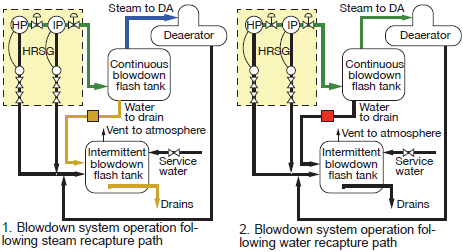
Fig 2 illustrates the alternative operating condition for the CBS. The thermal drain trap (red) is isolated from the drain line. Hot water moves from the HP drum to the IP drum to the flash tank to the deaerator (green). For this operating profile the control valves were reprogrammed to operate based on drum level. No water or chemicals are routed to the drain.
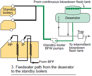
F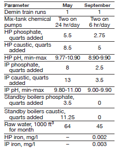 ig 3 shows the water path from the DA to the standby BFW pumps to the standby boilers (green). A detailed review of the water flow path shows that there are no system components—such as attemperators—that could be impacted by the introduction of low levels of phosphates.
Both May and September were zero-dispatch months. During May the plant was maintained in warm standby utilizing venting and blowdown operating profile described in Fig 1; September used the repurposed CBS described in Fig 2.
Results. The table compares operating parameters and chemical consumption for warm standby operation using the venting/blowdown scheme (May) and the repurposed CBS (September). The latter approach offers clear savings in water and chemicals.
Lighting upgrade makes Shoreham’s liquid fuel unloading area safer
High-pressure sodium lighting in the fuel-oil (FO) offloading area at Shoreham was dim, and existing light fixtures were heavy and prone to failure. Whenever one did fail, it was a challenging task requiring complete removal of the fixture from the underside of the roof in order to replace any failed components (starter, ballast, wiring, etc) The frequency with which these older, heavier fixtures were failing at the two-unit (LM6000) peaking facility owned by J-Power USA Development Co suggested that a more permanent solution was necessary.
The NAES Corp O&M staff engaged a vendor whose core business is to provide LED retrofit assemblies for most commercially available standard lighting fixtures. The aim was to replace the existing fixtures with LED retrofits that offer a much lower profile, thus preventing the bases from being impacted by the wind (the most common cause of failure of the older style models).
Cost also was an important consideration because replacement parts for the existing light fixtures were proving more and more expensive, and harder to come by.
Good results. Since replacing all the fixtures within the FO offload area with LED retrofit kits, there has not been any unexpected maintenance, says Plant Manager Kenneth Ford. The low profile of these lights secures tightly to the box mounts, so wind is no longer a factor. Plus, the area is dramatically brighter, providing much safer walking and working surfaces for plant staff.
From a financial view, the LED retrofit kits, on average, were less than half the cost of replacement incandescent fixtures.