Please bookmark our new web location at www.7Fusers.org
Reminded Outgoing Chairman Ben Meissner of Progress Energy Inc and Incoming Chairman Sam Graham of Tenaska Inc as the 2012 meeting of the 7F Users Group drew to a close in San Antonio, May 18. Earlier in the week, Meissner had walked attendees through the website, telling the assembly that the new online home for the organization is operated by the user group for its owner/operator members.
Further, that the previous website, hosted by a third party, would likely remain active but would no longer be supported by the steering committee.
Meissner demonstrated, using a series of slides, how the new website offers better archival search capability, easier access, and improved functionally compared to the previous portal. The group’s forum and presentation archives are available to user members on the new site.
 All future conference announcements, registrations, etc, will be conducted via 7Fusers.org. Certain information from the OEM will be there as well, along with the forums of great value to users (discussion, emergency, spare parts, etc). An email interface is included as part of the new forum setup; alternatively, users can go directly to the forum to create or respond to posts.
Existing user profiles have been uploaded to the new website, but you have to log onto the new site to register your password. If you’re a 7F user and never registered on the old site, go to www.7Fusers.org, click “Apply” on the horizontal toolbar at the top of the page, and sign up today. No charge. If you encounter any problems, contact sheila.vashi@7Fusers.org.
Immediately following the announcement of the new website, Meissner polled attendees to learn more about them. About half of the audience, by show of hands, said this was their first 7F meeting. Well over half the group had at least two years of experience operating and maintaining the GE engine, with about 40% saying they had participated in at least one major inspection. Units in peaking, cycling, and base-load service were represented about equally.
The starts leader in the room was over the 3000 mark; six engines were said to have recorded more than 100,000 operating hours. More than half the group had GE long-term or parts services agreements; about 30% self-performed maintenance.
Mission statement
7F Users Group Inc is organized to provide an open forum through conferences and technological aids to the owner/operators of 7F combustion turbine/generator systems for effective communication, discussion, and information dissemination regarding the operation, maintenance, inspection, troubleshooting, and repair of such systems to maximize equipment performance and reliability. These purposes will be achieved through providing an opportunity at meetings, conferences, company email, and website for the open exchange of ideas among owner/operators and owner/operators with vendors.
‘7F Week’ highlights
By the time Meissner opened the forum portion of the 21st annual conference on Tuesday morning at the Westin La Cantera, many of the more than 250 owner/operators in attendance, a record, had already participated in a day of special events. Monday, May 14, featured an eclectic program that included a tour of Pratt & Whitney Power Systems’ San Antonio shop, a workshop on heat-recovery steam generators conducted by engineers from HRST Inc, a golf tournament, and a special session on 7F rotor dynamics, vibration analysis, and troubleshooting developed by GE Energy. A reception and dinner completed the day.
The golf tournament, which began at 8 am on one of the host hotel’s two onsite courses, was dominated by players from the 108 participating equipment and services providers. The morning-long HRSG Spotlight Session focused on fatigue cracking and was attended by about three dozen users. Amy Sieben, PE, and Scott Wambeke, PE, divided up the subject matter, with Sieben covering fatigue and other failure mechanisms in superheaters/reheaters and panelized economizers and Wambeke handling return-bend economizers and steam-drum nozzle cracks.
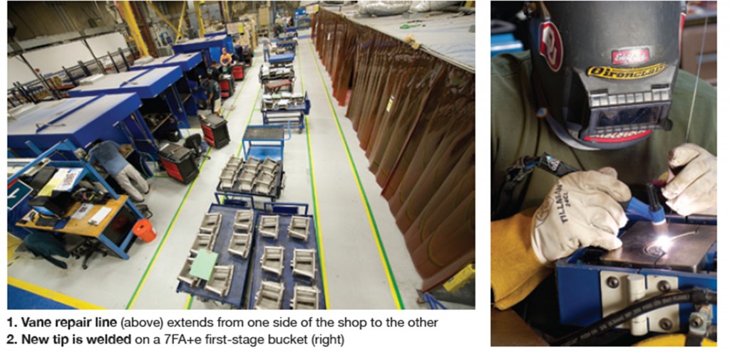
The approximately 100 users who visited the PWPS shop found a bright, modern repair facility with the latest inspection and repair tools and efficient production lines (Figs 1, 2). The facility is a one-stop shop—strip to ship—for inspection, refurbishment, and repair of F-class parts.
General Manager Gerald D Hill and his team of knowledgeable tour guides told the gas-turbine owners and operators that, in addition to restoration repairs, PWPS pursues design improvements with the goal of providing refurbished parts that are “better than the original” where possible. The collaborative process of component improvement involves (1) identification of issues based on field experience, (2) re-engineering and modeling of improved parts, (3) laboratory validation, and finally, (4) field validation.
The users-only sessions on Tuesday covered the 7F compressor, safety practices and lessons learned, controls, and auxiliaries. Vendor presenters included PSM, ExxonMobil Lubricants & Specialties Co, National Electric Coil, and Advanced Turbine Support LLC. Wednesday’s user-only lineup featured a combustion and turbine session, generator session, and open discussion before presentations by Environment One Corp, Praxair Surface Technologies Inc, PWPS, and Turbine Technology Services Corp, among others. Vendor fairs, including dinner, completed the Tuesday and Wednesday programs.
Thursday was GE Day. Presentations and discussion covered the entire engine from the air inlet house through the generator, capped off with a reception and OEM product fair. Friday’s program, which ended at noon, featured parallel sessions on D-11 and A-10 steam turbine maintenance and GE controls and diagnostics.
User presentations, discussion
The closed sessions at most user-group meetings serving owner/operators of frame-specific gas-turbine assets were structured similarly until recently. The standard formula was to start at the inlet air house and work back through the engine covering, in turn, the compressor, combustion section, turbine, generator, and control system. Session moderators would stimulate discussion using key words, recent experiences announced on bulletin boards, etc.
Example: “Who’s not getting expected life from their air filters and what are you doing about it?” Air filters typically were good for 30 minutes of discussion. It seemed that everyone had an opinion or experience to share on this subject. Meeting after meeting many of the same experiences were shared—certainly fine for first-timers, but not many ideas for the veterans to take away. Interspersed between discussion sessions would be one or more relevant vendor presentations. With this format, the questions raised and the ensuing discussion often were predictable.
The 7F, 501F, and 501G user groups have broken the mold, contributing to a higher level of energy at conference activities. All participants benefit from the new format, which has the following key elements:
- Steering committees deep in numbers and knowledge.
- Active participation by all steering committee members, both in making or sponsoring presentations by owner/operators and by contributing to and facilitating discussion forums.
- Eliminating vendor presentations from the user-only sessions and encouraging greater participation by equipment and services suppliers in forums held just prior to the vendor fair. At the 7F meeting, which had exhibitions on two evenings (different vendors each evening), there were six 45-min presentations by suppliers each day, conducted in two time slots following the afternoon break (three companies presenting in parallel in each session).
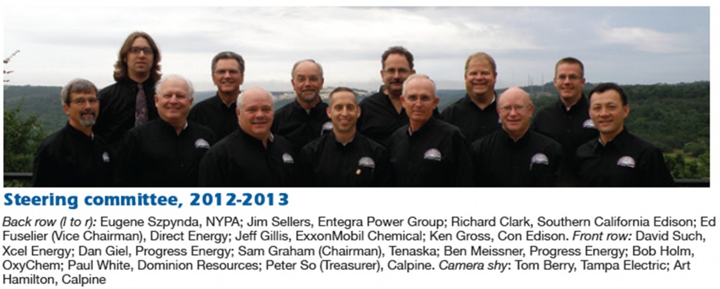
The 7F steering committee, 15 members strong, has a good blend of experienced “youth,” hard-nosed O&M managers, and engine experts with more than 25 years of industry service. One of the meeting’s non-technical highlights was the recognition by the current steering committee of two of the user group’s founding members in attendance, Pierre Boehler of GenOn Energy Inc and Bill Wimperis of Constellation Energy.
Wimperis, who chaired the first several 7F conferences, represented Baltimore Gas & Electric Co at the first meeting 21 years ago; Boehler was working for Potomac Electric Power Co at that time. Both engineers continue to serve the industry as members of the 501G and CTOTF steering committees, respectively. An interesting contrast: The first 7F meeting was attended by 14 managers and O&M personnel from four electric utilities, this year’s conference hosted more than 250 user attendees from perhaps a hundred generating companies—both regulated and unregulated.
In round numbers, there were a dozen user presentations at the San Antonio conference and they stimulated hours of open discussion so compelling no audible buzz from sidebar conversations was in evidence—unusual for a large audience in a cavernous ballroom. Critical to discussion management is having a team of experts on the floor to clarify questions where necessary and to answer them when others present cannot. The 7F steering committee does this to perfection.
Compressor section
The first user to present said he was concerned by the migration of compressor rotor-blade spacers discovered on two 7241s during their second HGPs. The units had about 1800 starts each but were transitioning from a starts-based regimen to base-load service. The units’ first majors probably are two years off. This owner/operator was not sure what should be done to address the migration issue, if anything, and asked colleagues in the audience to share relevant experience.
His investigation revealed no vibration problems resulting from spacer migration. In fact, calls to several users before making the trip to San Antonio did not uncover any vibration issues in the fleet that could be linked to spacer migration. The OEM’s response, he said, was “don’t worry.” However, GE expressed some concern that if the migration had occurred in rows 7 and 8, where the spacers align, a combined migration of the two rows could happen in the future.
Four attendees said spacer migration had occurred on their machines but there had been no negative effects. One of these users said he used to work for the OEM and had seen many instances of migration but no problems resulting from that movement. Yet another owner/operator had experienced migration on Frame 5s and 7EAs and thought it might be the result of poor craftsmanship—specifically, poor staking.
Someone else said that if just one or two spacers migrate it’s one thing, but if several in a small section of the rotor move, then you could throw the unit out of balance. He reported seeing this on peaking machines and attributed the migration to “thermal ratcheting.” A few others confirmed this based on their experiences with 7B-EAs. The OEM reportedly did field restaking for one user to correct for movement of one spacer.
Is your S17 solution the right one? A user reported that the back ends of some of his company’s 7EAs and 7FAs have had issues. The OEM recommended a shrouded S17 to strengthen the back end of one FA, but material distress was identified when the unit was opened up a year later. Some attendees seemed surprised to learn there are several S17 designs. The latest has staked bolts, older version welded bolts. Washers can be used, or not. In some instances where they have been used, washer rotation has caused rapid wear. Another variable: Some bolts have two tack welds, some one.
Discussion included mention of fretting on the ID shroud face near where adjacent vane segments butt against each other, as well as heavy wear in the V-seal slot. The amount of clearance between the shroud and S17 airfoil tip was brought to the floor. A couple of users measured gaps of up to about 30 mils; group consensus was that one-third that would be better and probably would mitigate the wobbling of parts experienced in some instances.
It appeared there were more questions than answers regarding S17 issues and that the discussion was likely to continue next year in Greenville (May 20-24, 2013 at the Hyatt Regency), if not sooner in the forum on the group’s new website at www.7fusers.org.
Machining might be best option for removing R0 blades to avoid damaging the wheel. One user provided a short presentation on the care required to remove compressor blades without galling. Ice damage on one of his units, initiated by cooling-tower drift, dictated the removal of R0 blades for repairs.
A 1-ton come-along and air hammer were the tools selected for the extraction which proved particularly difficult, galling 17 blades in the process. The high edges on the gall were blended to get the machine back into operation. Replacement of the first-stage wheel and R0 blades is scheduled for next year. This plant online water washes daily, offline twice annually.
Follow-on discussion revealed that a leaking wash-water valve (with the pump off) was the underlying cause of icing at another plant. In addition, a user attested to the difficulties one can face trying to remove R0 blades. He recommended machining out blades to avoid ruining the first wheel and having to replace it at significant cost. The attendee said it took two days of around-the-clock effort to machine out the R0 blades on his engine.
Discussion highlights:
- Most packages the OEM has are for the flared fleet, not unflared units. Example: There are no Package 2s for unflared units.
- Question to attendees: Any experience with OEM’s new Enhanced Compressor? One user reported having a problem-free 8000 hours on one engine.
- R0 dovetail indications building, a user reported. Be prepared for “discovery,” he said. Continuing, he suggested to colleagues that they not get complacent regarding inspection. “As the fleet ages, people who never found any indications are now finding them.”
- Bigfoot mod: Stator twisting in the case slot occurs early and appears to slow/stop. Future impact, if any, is unknown. More than 60 mods have been installed in the fleet, according to one user, and all show signs of twisting. The OEM reportedly has told users that twisting does not impact performance or reliability. It was said that no plant has yet removed stator blades from a unit with a Bigfoot mod.
- An attendee suggested that users look for cracking on the R17 wheel rim; about half a dozen users said they had found it. Recall that the 17th stage incorporates the stub shaft. Another participant said cracking is expected by the OEM and the wheel is designed to accommodate small cracks (up to 0.125 in.), which can be blended out. However, if you blend and can’t remove the crack, that user said the crack will propagate faster than if no blending had been done.
- Another user said there also are cracks on R14, R15, and R16 wheels, but they generally are not visible to the naked eye. These cracks are said to run inward from either the front or back face of a disk. You don’t know how deep these cracks are until you grind them out. It was said that no failures have been attributed to this type of cracking, “so don’t worry about it.”
- Audience poll: One user still is operating with P-cut blades.
- Make sure R0 blades are properly staked. Over-staking, it was said, can compromise the ability of a biscuit to lock a blade in place.
Air inlet house
A fire that consumed an inlet filter house pointed to shortcomings in plant’s safety plan.
A contractor hired to install prefilters selected a halogen lamp to provide more light in the narrow passageway between the prefilters and conical/cylindrical final filters. An extension cord, draped over the access-door threshold, brought power to the lamp, located about 5 ft inside the door.
Unsafe work practice #1: Never run electrical cords, hoses for cutting torches, welding cables, etc, through open doorways. The contract crew said the door had been wired open, but photos suggested otherwise. Workers took a break and left the light on, then decided to quit for the day because job progress was ahead of schedule.
Unsafe work practice #2: This unplanned work stoppage was not reported to responsible plant personnel and the light remained on. The high heat produced by the halogen lamp ignited combustible material in the inlet house and smoke poured out from the structure. The fire was promptly reported to the control room and emergency procedures were enacted.
Volunteer firefighters arrived within about 20 minutes and took about three-quarters of an hour to extinguish the fire, even though about 80% of the “fuel” had been consumed before the firefighters arrived. The inlet filter assembly and transition duct were a total loss. The support structure suffered no fire damage; silencer panels, inlet-bleed-heat components, and downstream ductwork were salvageable after a thorough cleaning.
Unsafe work practice #3: The danger of halogen lamps and the OEM’s recommendation not to use them was covered by Technical Information Letter 1368-2 but went unheeded. Read and understand all TILs recommended for your units and act accordingly, the speaker urged. This same TIL suggested warning/caution signs on the dangers of working in the inlet air house, but they were not posted. Not surprisingly, the Job Hazard Analysis developed for this project by plant personnel never warned of fire hazards.
Unsafe work practice #4: The safety analysis conducted by company personnel after the fire revealed that the lone door in the filter house accessed the lowest catwalk for the filter assembly. The three catwalks at higher elevations were accessible only by ladder. Had there been workers at one or more of the higher elevations when the fire began, they probably would not have survived. Egress panels were installed at each of the catwalk levels. The replacement inlet air house was installed without lighting; plans are in place to add retractable LED lighting.
A key take-away from this incident was that you cannot over-communicate about safe work practices, proper tool selection, and hazardous conditions. The speaker suggested that his colleagues implement a “Friendly Eyes” program if they didn’t already have one. It involves taking experienced, safety-conscious employees from another site and have them walk-down your plant to identify unsafe work practices. They will find things the resident employees see regularly and accept, but which may not be in the best interests of health and safety.
Combustion dynamics
The user controls expert who last year offered an objective evaluation on the pros and cons of combustion dynamics monitoring systems (CDMS) installed on 7F engines in the fleet he serves returned to the podium in San Antonio. The speaker said he believes the following three CDM systems are acceptable for powerplant use:
- PSM’s AutoTune.
- WoodGroup’s (Gas Turbine Efficiency last year) Ecomax™.
- The OEM’s OpFlex™ AutoTune.
Last year most of the engineer’s experience was with AutoTune; only two engines had been equipped with Ecomax. OpFlex was not considered for deployment because of its cost. What a difference a year makes: Here are the highlights of what he had to say in San Antonio:
- PSM’s AutoTune now has more than 30,000 hours of operating experience in his fleet. Recent upgrades included firing-temperature optimization up to 2420F (going higher still this summer) and an events counter for reporting how many times the system has tuned and what’s been tuned.
- GE’s OpFlex now is offered at various levels to suit specific requirements and pocketbooks.
- Ecomax has been commissioned on six engines in the speaker’s fleet with six more being installed. Experience is now coming in from more than 16 units. He reported the following:
- The system is user configurable and offers control-curve optimization—that is, it optimizes base-load output.
- Post-outage tuning is not required.
- Fuel temperature and firing curve knobs are provided to facilitate tuning.
- Operation is flexible. Example: Ecomax will still tune for NOx when the CDMS is down.
- System’s ability to prevent lean blowout (LBO) seems apparent.
- Monthly reports are provided on low-NOx tuning events that likely have prevented LBO.
- Power optimization is noticeable.
- Installation requires minimal downtime and proceeds in a relatively smooth manner with only minor issues.
Bearing issue
A user offered a step-by-step procedure for installing thermocouples in generator bearings. It was obvious that he hadn’t intended becoming an expert on the subject, but when bearings sent out for rebabbiting came back without thermocouples, someone had to install them.
Saving time by doing the job in-house seemed like a reasonable objective. After all, how difficult could the task be? Everyone who has ever spent time on the deck plates knows there’s usually more to any job than meets the eye. So it was in this case. You can access the procedure at www.7Fusers.org.
Sensitive rotors
A scholarly, yet practical, presentation by a power-company vibration expert walked users through field data analysis, observations, and conclusions of 7F thermal transient vibration. This is another presentation you may want to review at www.7fusers.org. Perhaps the best part, and critical to easy understanding of the subject matter, is that the speaker prepared an old-school paper (no sketchy PowerPoint), complete with 19 figures.
The utility consulting engineer told the group that all rotors have a thermal transient characteristic. For some, the thermal transient can be sufficiently small as to be considered non-existent. On other rotors it can be so severe on a cold start that it can make the rotor go into vibration alarm, cause a load runback based on vibration amplitude, or even cause the unit to trip on vibration amplitude. For most rotors, it is somewhere in between. The source of this transient appears to be a combination of the basic design, manufacturing tolerances, and variations in the assembly process at the factory/shop.
When it has been determined that a rotor has a thermal transient that must be addressed, the expert said, required data should be plotted in polar format for a cold-rotor-condition start, beginning immediately after reaching the full-speed/no-load condition and ending at the steady-state base-load condition. Once a rotor’s transient is quantified, a corrective course of action can be determined.
Depending on how the unit will be operated, either tactical balancing or prewarming of the rotor before the actual start usually are the best options. Should the transient’s extreme points ever become so large that the transient cannot be controlled—even through warm starts and balancing—then the rotor must be sent to a shop for repair.
Vendor presentations
The vendor community has a great deal to offer gas-turbine owner/operators. Plant and headquarters personnel don’t have all the answers, neither do the OEMs. Small businesses serving the electric power industry, in particular, are highly motivated to understand the challenges facing generation O&M personnel: Timely and effective solutions are conducive to a strong bottom line.
Summaries of several 2012 vendor presentations available at www.7Fusers.org are below. Two editors can’t get to all of them and, like you, have to make choices.
TIL review
Advanced Turbine Support LLC
When members of the borescope inspection team from Advanced Turbine Support LLC talk, virtually everyone with responsibility for gas-turbine assets pays attention. Reason: Rod Shidler and company generally don’t tell you what you want to know, they tell you what you have to know to keep running. Field Service Manager Mike Hoogsteden’s presentation to a packed room discussed the importance of technical information letters (TILs) 1509-R3, 1638, and 1795 in reducing operational risks.
Most of what Hoogsteden had to say in San Antonio he and colleague Dustin Irlbeck reported to the industry last December by webinar. CCJ ONscreen’s Scott Schwieger coordinated and produced that event, which was sponsored by Dresser-Rand Turbine Technology Services.
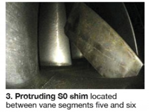
For his 7F presentation, Hoogsteden added a section on TIL 1562 to stress the importance of monitoring the condition of compressor shims and the corrective actions necessary to mitigate the risks of migrating shims on both E- and F-class machines (Fig 3). There are 20 possible shim locations in the first five stages (0-4) of 7F units and they are spaced approximately 60 deg apart from each other.
Most people like stats and Hoogsteden gave the owner/operators some numbers to ponder with what he called the ATS Scorecard. Keep in mind when reviewing these data that, at the time of the 7F meeting, there were said to be 821 engines in the fleet, with the leaders at about 126,000 factored fired hours and about 3500 factored fired starts.
TIL 1509. ATS has completed more than 2000 in-situ inspections since 2001, identifying more than 200 cracked rotor blades, over 70 S0 cracked vanes (six in unflared compressors), and three S1 cracked stator vanes.
TIL 1638. ATS has completed nearly 1100 in-situ inspections of R0 rotor blades (P-cut, standard, and enhanced) over the last five years, identifying 55 R0 blades with cracks adjacent to the P-cut relief, 55 R0 blades with cracks in the suction-side mid-span dovetail fillet, two R0 blades with cracking on the suction-side mid-span dovetail sloped face, two R0 blades with cracks in the pressure-side dovetail fillet (both in the leading and trailing edges), and two cracked R1 rotor blades.
All of the above indications have been validated; there were no false positives.
Compressor solutions, field experience
PSM, an Alstom company
SRO, standing room only, is no surprise when PSM presents at a user group meeting. Chris Johnston, a senior R&D manager, moved quickly through understandable technical detail in bringing users up to date on his company’s 7FA compressor solutions and field experience.
Johnston divided the compressor section of his presentation into four parts: R0, S0-S4, S13-16, and S17/EGV (exit guide vanes).
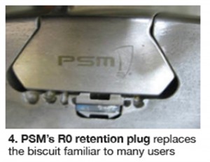
PSM’s solutions have been operating in the fleet for four years with parts installed in more than 30 units, he said, adding that fleet-leader sets have been validated by way of on-going in-situ, destructive, and dimensional inspections. The company’s redesigned R0 blade, which has a different airfoil shape than the OEM’s, is meeting expectations in units that fog and online water wash. Its R0 retention plug replaces the biscuit familiar to many users (Fig 4).
Success with the flared R0 airfoil prompted development of an unflared R0, the R&D manager continued. The new offering also operates without restriction and is now running in four or five engines. The development approach used PSM’s successful methodology: field assessment, problem identification, solution implementation, and validation.
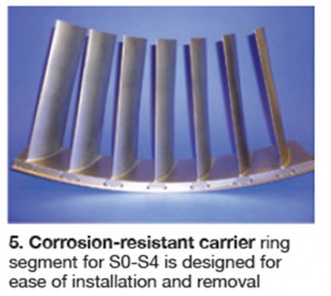
S0-S4 field issues, including high-cycle fatigue (HCF) and corrosion concerns, have been addressed with a redesigned S3 airfoil and corrosion resistant carrier ring (Fig 5). Johnston said PSM believes that the OEM’s S3 vane has the lowest design margin in this section of the compressor and required redesign to mitigate HCF failures initiating at its leading edge.
OEM vanes in S5-S16 have a history of hook fretting and other hook-fit issues. PSM’s S5-S12 vanes remain stator singlets, redesigned to better accommodate the circular case. For rows S13-S16, the company’s “hook ring” packed design provides increased damping.
The second part of Johnston’s presentation concerned the 7FA GTOP3 upgrade. GTOP is the acronym for Gas Turbine Optimization Program. This enhancement incorporates PSM’s low-pressure-drop combustion system and redesigned first- and second-stage HGP buckets and nozzles. The upgraded components have been operating since 2005 and have accumulated nearly 100,000 service hours. They are interchangeable with OEM parts.
The higher firing temperature allowed by the redesigned standard-life (24,000 hours/900 starts) first- and second-stage turbine buckets and nozzles can increase power output of a simple-cycle engine by 5% and improve simple-cycle heat rate by 1.3%, while still achieving less than 9 ppm NOx and accommodating turn down to 50% of the full-load rating. Extended-life (32,000 hours/1200 starts) airfoils are compatible with a 2% increase in simple-cycle power and a 1% improvement in heat rate.
Johnston noted the 22-MW gain attributed to GTOP3 for the company’s first combined-cycle install at a 2 x 1 plant. PSM provided field services, the gas-turbine TFAs, and tuning services. Third-party performance testing conducted before and after the outage validated a 5.2% increase in power for one GT and 5.1% on the other. Efficiency gains were 1.6% and 1.5%, respectively.
Advanced coatings
Praxair Surface Technologies Inc
Don Lemen walked 7F attendees through the company’s advanced coating systems for gas-turbine compressors, combustors, and turbine parts. Many participants in the break-out session knew Praxair best for its fir-tree coating to prevent bucket rock, which is championed at many user-group meetings by Mike Romero.
Lemen began at the compressor inlet with a backgrounder on Praxair’s titanium nitride (TiN) solution to help control—possibly eliminate—the liquid droplet erosion of R0 blades associated with both water washing and fogging for power augmentation. Water-jet laboratory testing suggests the company’s coating system is good for more than 50,000 hours of service.
If corrosion of compressor airfoils is an issue, Lemen suggested the SermeTel® 5380 DP® coating system, which consists of a closely packed aluminum-filled chromate/phosphate base coat, sealed with a chemically inert chromate phosphate top coat. It is said to protect stainless steel and ferrous alloys at temperatures up to 1200F. On dimensionally critical surfaces, precision coating thicknesses down to 0.3 mils can be achieved.
Zircoat® vertically cracked coatings for combustor parts, buckets, and nozzles requiring the highest level of thermal protection were covered next. The ultra-pure YSZ coating in this family (patent pending) was said to offer long-lived erosion resistance and toughness. A discussion of abrasive tip systems closed out the presentation.
Hydrogen control cabinet
Environment One Corp
Many hydrogen-cooled generators—including all those driven by 7F gas turbines—incorporate a scavenging-type seal oil system to prevent the escape of hydrogen from the generator casing and to prevent air from entering the generator case. A critical component in this type of seal oil system is the hydrogen control cabinet. It houses the principal instruments required for supervision of the hydrogen system and the controls for regulating the rate of gas scavenging.
Rob Preusser, manager of utility products and field service, conducted a short course on the company’s Dual Hydrogen Control Panel familiar to most who attended the session. By way of background, E/One has more than 1500 hydrogen purity analyzers and 1300 generator condition monitors installed worldwide. Preusser covered a lot of ground in his 40 minutes or so at the podium, including the following:
- Detailed description of the generator gas analyzer, including physical components and electronics.
- Principles of operation.
- Flow configurations.
- Interface connections.
- Maintenance requirements.
- Troubleshooting.
- Solutions for resolving issues such as oil contamination, failure of power supplies, obsolete circuit boards, etc.
Given the detail of Preusser’s presentation you might want to consider using it as the basis for technician training.
Open-architecture control solutions
Turbine Technology Services Inc, Rockwell Automation
TTS is probably recognized best by the greater gas-turbine community for the hundreds of control-systems upgrades it has performed over the years, and by 7F users because of Mitch Cohen’s insightful presentations. Kevin Giroux of TTS and Rockwell’s Rick McLin brought users up-to-date on open-architecture alternatives for the replacement of ageing 7F control systems—such as the Mark V, which will no longer be supported by the OEM after 2014.
A primary goal of the presentation was to assure owner/operators that the triple modular redundancy feature of the OEM’s control systems was also integrated into the open-architecture offering by TTS/Rockwell. Recall that TMR uses two-out-of-three voting to assure a highly reliable control system. Specifically, any single-point failure can be diagnosed and repaired while the system is in operation.
Giroux and McLin also stressed the advantages of open-architecture systems over the “black box” offerings from the OEM, including the following:
- Control code is available and accessible.
- Complete system maintenance is possible. This includes software edits, configuration changes, module additions, etc.
- Ease of integration into other plant-wide systems.
The slides from this presentation are easy to follow and offer a refresher on how triple-modular redundancy works. The PowerPoint certainly is worth a review by users contemplating control-system replacement. Visit www.7Fusers.org.
Varnish no more
ExxonMobil Lubricants & Specialties Co
Jim Hannon of ExxonMobil Lubricants & Specialties Co opened his presentation on the subject of varnish solutions by telling the three dozen attendees in his session things virtually all of them knew: (1) where varnish can be most disruptive and (2) its negative impact in terms of unscheduled outages, extra maintenance, etc. But then he told them something most didn’t know: he had the mineral-oil solution that could cure their pain.
Hannon is an old “plant guy” who knows his equipment. He took that knowledge to Exxon where he learned lube-oil technology and became a solutions provider. Most of his presentation concerned how the company went about developing and validating the effectiveness of Mobil DTE 932 GT, which was formulated specifically for GE Frame 6, 7, and 9 applications where varnish control in the hydraulic system is most needed. An independent study of nearly 200 generating facilities powered by more than 600 7EAs and 7FAs revealed that 40% of the gas turbines surveyed had experienced, or were experiencing, varnish issues.
Much of the material presented by Hannon is available in “Vanquish varnish to improve gas-turbine reliability,” which appeared in the CCJ’s 2011 Outage Handbook. A bar chart included in his presentation showed how well DTE 932 stacks up against the competition based on proprietary rig-test evaluations conducted by ExxonMobil Research & Engineering Co. To dig deeper, access the presentation at www.7Fusers.org.
Generator rewind
National Electric Coil
If the gas-turbine user group community were to vote for a generator champion, National Electric Coil’s Howard Moudy would probably win hands down. Well known, he attends most user meetings and speaks passionately on the maintenance and overhaul of these vital rotating machines. Moudy’s presentation at 7F XXI was on “Considerations in purchasing quality stator windings and rewinds.”
His goal was to provide much needed perspective on what steps owner/operators should take to assure that their project expectations will be met. The specification is critical, he stressed, and challenged attendees to think about the possible improvements they could make by not replacing in-kind. All capable suppliers have the engineering ability to upgrade an existing coil, Moudy said. For example, thin insulation material available today allows you to increase the amount of copper in an old machine, reducing I2R losses; thinner strands can reduce eddy current losses.
His slides walked the users through the coil manufacturing process, covering types of ground insulation, winding fit-up inspections, etc. Tests described included blackout, corona camera examination, hi pot, voltage endurance, and thermal cycling. CCJ


