Steam can flow backwards and erode trailing edges of last-stage turbine blades
Steam turbines (ST) often exhibit leading-edge erosion on the last-stage blades (LSB) of the low-pressure (LP) section. This is from moisture forming as steam condenses prior to passing through the entire machine. The micron-size water droplets impinge on rotating-blade surfaces and remove material—mostly from the leading edge. It is a well-known problem and has been an engineering challenge for both OEMs and equipment owners since about the time condensing steam turbines were introduced more than a century ago.
Combined-cycle steam turbines often operate at part load, introducing a new problem to the LSB row: Erosion of the trailing edge (TE). Brent Gregory and Ryan Yamane of Creative Power Solutions (CPS), Fountain Hills (Phoenix), Ariz, told the editors they are seeing cases where a flow condition, developed in the ST itself, has caused TE erosion of LSBs. While last-stage steam-flow behavior at partial load may be well understood by turbine OEMs, that may not be the case for condenser manufacturers, which play significant roles in determining ST discharge conditions.
Integration of the ST with the condenser must be fully understood to maximize pressure recovery in the diffuser, allowing for optimal flow behavior. Gregory said recent work performed by CPS explains, in part, how wet steam in the condenser can re-enter the ST by being “pulled” into the LSB from a massive flow recirculation caused by turbine and condenser architecture.
Gregory first saw the problem while designing LP turbines for aircraft engines. Turbine designers in that industry sector have a particular problem when designing blade rows because the LPT has significant swings in its operating point, depending on what the pilot is requesting as the engine duty—that is, take-off, cruise, taxi, etc. Each duty demands a different air flow requirement on the fan; hence, the LPT does not have a set design point.
Usually, efficiency is optimized for the cruise condition because the airplane will spend a significant amount of time there. What may happen under such scaled designs is the flow in the turbine may not have sufficient capacity to fill the annulus and flow will migrate off the hub or inner walls of the flow path, due to the centrifugal forces overtaking the momentum of the air flow, and be forced to the tip or outer walls.
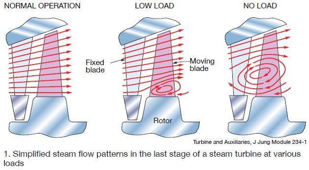
Something similar happens in STs at no-load flow conditions or when steam flow is reduced to reduce shaft power output. The ST, which is designed for base-load operation, experiences a flow separation at part load inside the turbine flow path which extends downstream (Fig 1). The void that forms in the turbine extends into the downstream hardware and impacts the performance and endurance of the last few stages of the LP turbine.

In aircraft engines, advanced design techniques within the blade rows can be applied to prevent this phenomenon. In principle, the same technology could be applied to the last ST stage, but to Gregory’s knowledge it has not been done. Another solution is required.
While wet steam may be the main culprit for TE erosion, Gregory and Yamane pointed to multiple sources of water droplets in water-cooled combined cycles capable of exacerbating the erosion mechanism. Examples:
- Exhaust-hood sprays, designed to keep the exhaust diffuser and expansion joint from overheating, inject water into the steam flow immediately downstream of the LSBs.
- Curtain-water spray systems for quenching high-enthalpy bypass steam introduced to the condenser during startup, shutdown, and/or GT blending in combined cycles with multiple engines.
- Droplets, which may have small diameters at injection, impinge on condenser supports and other parts, coalescing into larger droplets that can be drawn back towards the LSBs and contribute to TE erosion.
The diffuser directing turbine steam to the condenser also is designed to operate at one condition. Because there are no variable pieces of hardware in the flow path to accommodate the changing conditions of turbine flow at partial load, the diffuser also is operating in a sub-optimal way. This degrades turbine performance and may even cause structural damage.
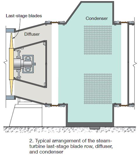
Gregory said CPS recently had the opportunity to review such a setup with a customer. The arrangement was of typical turbine/diffuser/condenser architecture, similar to that in Fig 2. Extensive CFD was performed, with the OEM design team providing accurate turbine conditions at the plane of the turbine discharge.

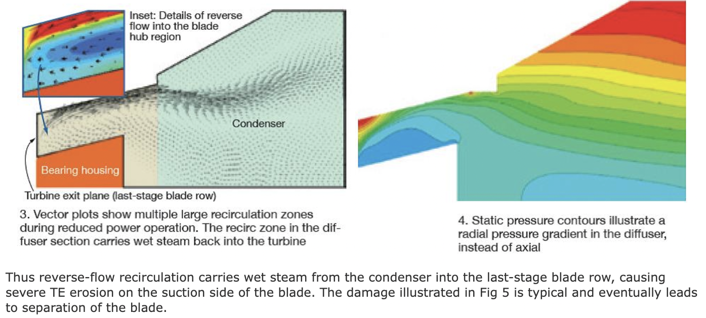
The CFD model accurately predicted condenser and diffuser performance. Recirculating eddies caused by the large separation of flow off the inner diffuser wall and again off the back side of the bearing housing enabled wet steam to flow upstream and re-enter the turbine in the zone of separation. This can be seen in the CFD analysis as reflected in Fig 3 (velocity vector) and Fig 4 (pressure).

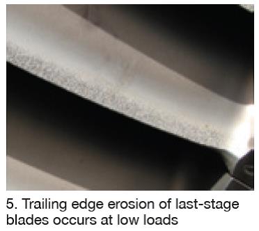
Thus reverse-flow recirculation carries wet steam from the condenser into the last-stage blade row, causing severe TE erosion on the suction side of the blade. The damage illustrated in Fig 5 is typical and eventually leads to separation of the blade.

Gregory offered several recommendations on how to limit the phenomenon’s impact. Most obvious, he told the editors, is to run the turbine at its continuous full-load rating. At that condition, LSB TE erosion is unlikely. If the turbine must operate regularly at part load, he suggested regular inspection of the LSBs for erosion and of the water injection systems mentioned earlier to verify their proper operation. Regarding the latter, it is important to see that all nozzles are in place and in good condition and there is sufficient supply pressure to assure proper droplet atomization.
CPS engineers have found that, in some cases, damage occurs during unit starts and may become visible after a particularly busy production season involving daily starts. If you find erosion during a LSB condition assessment consider conducting a root-cause analysis because erosion will likely get worse with part-load operation. Perhaps only a change in operating procedures will deliver the desired result.
As the interview concluded, Gregory said that CPS has formulated unique solutions that could potentially address the erosion issue for certain turbine back-end configurations. The upgrades, he continued, are competitive with the costs associated with periodic replacement of LSBs to guard against the possibility of a catastrophic blade failure and the significant financial impact of an unscheduled outage. CCJ


