
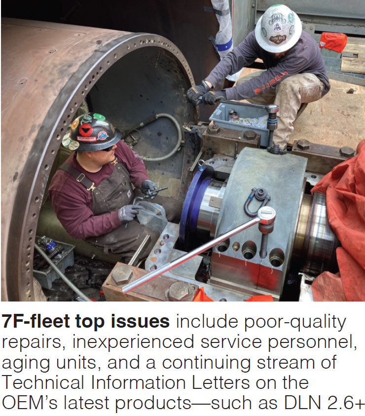
Relative to what was presented at previous meetings, the matrix of issues facing users expanded and the sentiments about the OEM didn’t get any kinder at the 2024 7F Users Group Conference, held in St. Louis, MO, May 20-24. Those wishing a refresh on earlier conference summaries can refer to CCJ, No. 78 (2023) and CCJ No. 74 (2022) or using search function above. Those wishing to participate can attend the upcoming meeting in Birmingham, May 19-23, 2025.
Emblematic of the frustrations are the following near-verbatim quotes from users during the various sessions. Note: More than one user noted that OOEMs and major GT service industry players are facing similar challenges:
- We’re going to have idle units because of supply chain issues
- Our recent ST/G outage highlighted the importance of improved collaboration and execution alignment with the OEM because of numerous avoidable issues
- There appears to be an opportunity to strengthen communication between OEM executive leadership and field operations teams to promote better outcomes
- Site engineers from the OEM would benefit from additional field experience to better support complex site activities
- Post-outage, we’ve observed recurring tube leaks, underscoring the need for enhanced quality assurance during OEM departures
- It takes too long to publish a TIL (technical information letter) after it has been initiated
- Lead time for critical spares is up to six months
- In-shop work is a black box when it comes to communication
- We’re seeing opportunities to improve accuracy in parts fulfillment and ensure alignment with site specifications
- QA/QC sign-offs on some hardware, such as bolts, could be more thorough to ensure installation integrity
- Our last outage extended from 70 to 140 days due to stator bar issues, pointing to the need for tighter process controls
- We’ve noticed consistent resistance when addressing certain issues with the OEM, and see potential in fostering more collaborative problem-solving
- After replacing a bearing twice annually, we recently discovered through the 7FUG that a long-term OEM solution already exists
- There’s a lack of clarity on the operational history (starts and hours) of R4P parts, and greater transparency here would enhance confidence and planning
You didn’t have to read between the lines to note the OEM, during its OEM Day (summary follows), acknowledged many of the user frustrations but struggled to offer satisfactory responses for the here and now, while deflecting to new processes, procedures, and investments expected to remediate user concerns going forward. One OEM representative acknowledged that “we’ve been humbled regarding quality.”
As always, the user presentations, summarized here (most posted online and available to members at www.powerusers.org), share invaluable lessons learned, experiences, updates on recurring issues, new issues to monitor, and post-mortems of safety events which enrich the entire community. It’s clear that larger owner/operators (O/O) continue to exert more control over their machines’ destinies by taking more responsibility for inspections, conducting more oversight of repairs, working with EPRI to solve problems, and collaborating even more with other users.
Check fuel delivery header vents!
Nothing is worse than hearing of loss of life at a plant. Folks who come to user conferences to share so that similar accidents elsewhere can be avoided deserve the highest praise. Representatives from owners of a plant with eight simple cycle 7FAs reported on the failure of a high-pressure (HP) gas-vent-pipe ball valve on a fuel delivery header which took the life of a worker.
The failure occurred after the GTs were isolated and workers were relieving pressure in the system. The worker opened the top vent valve first, but the bottom vent failed. Post-incident assessment showed that the wall thickness of the vent pipe was not suited to the service and a 90 deg elbow in the vent line created a thrust load which was not counter-balanced with bracing. The vent valves had been exercised several times before.
Further review showed that what was installed was not what was called for in the design. Hundreds of workers walked past that vent and no one caught the off-spec install. Other vents at this site were similar. Subsequent walkdowns of every site and every vent in the owner’s other GT plants revealed multiple locations requiring modification.
Weaknesses identified in the processes and procedures are (1) lack of oversight of the fuel delivery system compared to the GTs and (2) no standardized operating guide was available for clearing energy in the piping. Presenters cautioned that trying to establish a LOTO clearance in this part of the process created new safety issues.
Presentation slides are not available at the Power Users site, so network with your friends to access the details.
Combustor issues
Some of the newer F machine issues appear to be focused in the combustor area.
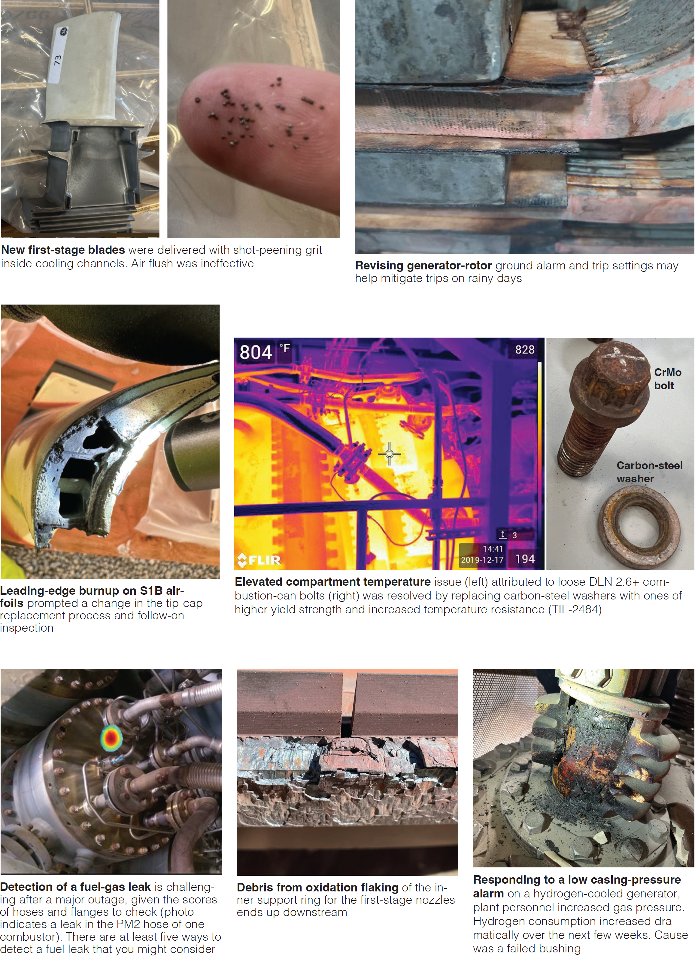
Inner support rings. Four 7FA.05 machines with dry low Nox (DLN) 2.6+, advanced gas path (AGP) tech package, and 32k hr hardware (COD 2020) experiencing one to two starts per day are suffering from combustor fallout, or oxidation flaking, caused by inner support ring (ISR) failures. The ISR supports the stage 1 nozzles. “Massive amounts” of debris end up on the transition pieces (TP) downstream of the combustor crossfire tubes.
Flaking was observed after 5000 hours and 350 starts in 2021 and progressively got worse over the next two years. ISRs were replaced in kind in 2022 with no improvement, replaced again in 2023, and replace a third time with “upgraded materials.” Replacing ISRs entails full removal of the combustor.
Photos of the site show an outdoor laydown area dotted with “unserviceable” TPs. Across the four units, 61 TPs have been replaced since the plant came on-line. Only seven made it to the 32k hot gas path (HGP) major. The presenter lamented that the OEM insisted that the .05 machine could handle this level of cycling and that no satisfactory answer has been offered, although an RCA is in the works. TIL 2364 addressing the situation was issued in the second half of 2022.
When the audience was asked if anyone had similar experience with .05s in high cycling service, no one responded. Excellent photos available in the on-line slide deck show the extent of the damage, as well as collateral issues, such as cracks across the PM1 fuel nozzle tip and across the effusion plate faces.
Combustor casing bolt washers. Washers seem so “elementary” until they are not. A large fleet owner/operator (O/O) reported on loose combustor casing bolts in 7F units with DLN 2.6+, initially observed in one unit after only three years operation. Some bolts had “spinning” washers, others were “backed out.”
Loose bolts create leakage pathways and elevated compartment temperatures. Subsequent evaluation showed that the design material was inadequate – it softens over time – and the washers were not properly torqued.
The O/O worked with the OEM to find a modification, resulting in TIL2484, which applies to several dozen machines in the fleet. At conference time, six units had new Inconel (ASTM A437 GRB4B) washers and the bolts’ torquing pattern and sequence was updated for all the units. The bolts are more expensive, and the revised install procedure adds a shift-man of work to an outage. Each unit has 910 of these bolt/washers.
Several in the audience noted that they have had forced outages or delayed operations as a result of this issue and others noted that they experienced elevated compartment temperatures, which were resolved after addressing this bolting issue. The TIL recommends replacing these bolts and washers at the next outage opportunity.
The presenter reminded the audience that the TIL applies to all 7F 2.6 and 2.6+ transition pieces in your inventory, including new and repaired versions. A slide in the deck details the new torquing procedure.
Liquid fuel flame detectors. Straddling the line between combustion and I&C, user explained how a large fleet owner/operator resorted to use of NOFD (non-optical flame detector) software for nine dual-fuel simple cycle units upgraded with 2.6+ AGP and enhanced compressor between 2017 and 2023.
Original flame detectors and upgraded versions kept fouling during liquid fuel combustion (though no problems were seen during gas firing), causing units to trip. Even after TIL2098 was issued, which called for changing the positioning of the detectors by shortening the length of the support tube assembly, the units still had problems. Detectors would “drop out” after a few hours once water injection was initiated. Other maladies are described in the slide deck.
TIL2428 was then released documenting issues with sensing degradation caused by water and fuel spray patterns fouling the detector lenses (slides offer clarity as to the level of fouling). The TIL recommends that sites apply NOFD software, a data-driven algorithm, to prevent trips during liquid fuel ops.
The rest of the slides elaborate on the software and logic, and experience with its use, summarized as “mostly good.” If you’re suffering from similar maladies, you won’t want to skip the slides on custom control and troubleshooting screens developed by one of the site’s engineers.
Hot gas path
The following summaries underscore how owner/operators (O/O) are conducting their own QA/QC and RCA activities as oversight on the OEM.
Stage 1 buckets. Presentation began with a review of S1B design changes from the 7FA through the 7FA.05/AGP. O/O Specialists now conduct post IA, precoat, and final inspections for all repaired S1Bs and final inspections for new S1Bs.
One recent finding was that broken reamers from the thermal barrier coating (TBC) process were discovered inside internal cooling channels of repaired S1Bs – the OEM apparently failed to do x-ray or borescope inspection of the final product before shipping. After returning the set, the OEM borescoped 92 blades and 22 had to be replaced with new.
Another finding was shot-peening grit inside the cooling channels of new S1Bs, which could not be removed by air flush. Masking during shot-peening apparently failed to prevent the grit from entering the holes. Again, the OEM did not perform x-ray or borescope inspections before shipping to the site. After they were returned, the OEM did x-ray inspection of 92 blades and 11 had to be replaced with new.
An audience member asked if they had to “push” GE to do x-ray inspection of the returns and the answer was yes. Another added they also discovered reamers in the cooling holes of sets of S1Bs from 2021, an issue that had been on-going for years. A third noted that they were seeing mid-span tip indications and cracks after weld repairs of single crystal blades after 900 and 2400 operating hours.
Defects in R4P S1Bs. Simple-cycle dual-fuel 7FA units with DLN 2.6+ and R4P parts, including modified .03 S1Bs, AGP-Tech S1N, AGP-Tech S1S, modified .03 S2B and S2N, began to experience leading edge damage after 300+ FFS and 3000+ FFHs. To pre-empt issues at the next outage, the O/O sent S1Bs in inventory out for x-ray inspection of the tip caps. Prior to late 2023, the OEM did not do x-ray inspection of tip caps.
Slides include photos from inspections but the list of findings include: internal cracks as long as 0.867 in., backwall strikes from foreign objects, push-through on internal walls from electrical discharge machining (EDM), and small cracks on trailing edges.
As a result of these inspections and RCA work, the OEM now performs x-ray inspection of all R4P S1B replacements and changed the tip-cap replacement process to (1) include new gages to ensure correct angle of weld prep and (2) more accurately locate the internal ribs to assure the correct cut of the tip cap over the ribs for welding.
Presenter stressed that they don’t yet know whether these changes will prevent leading edge damage caused by tip cap burnup. The first set of blades was installed in spring 2023 and were scheduled for BI in the fall of 2024. An audience member asked if there were any limitations on starts between BIs and the answer was no.
The presenter, in wrapping up, noted that the set of R4P S1Bs taken from a fall 2023 outage showed additional damage, including platform cracks on 12 pieces. RCA is on-going.
Blade vibration trip RCA. User experienced a vibration-initiated trip of a 7FA.03 which, upon investigation, resulted from a mass loss event when the 3rd stage blades all failed catastrophically. The unit had 130k+ operating hours at the time of failure. The failure is associated with creep degradation, clearly shown by the dark gray/blue boundary on one of the fractured blades, and faulty repair methods.
The repair was “years ago” and the O/O still doesn’t know the root cause. However, eddy current indications were noted by the OEM at the time of repair but were not shared with the O/O in the final report. Bottom line: O/O no longer uses S3Bs from the OEM repaired more than once. Three audience members reported experiencing similar failures, with one noting it happened three times in a row.
Generators
Leakage in water cooled generator. User recapped assessment of moisture, dust, and oil ingress and its impact on the insulation of the water-cooled generator rotor. During heavy rains and high humidity, the insulating capability drops to levels which can trip the unit on rotor ground fault. Site lost over $1-million in revenue in 2023 as a result of this issue.
A variety of actions were taken to prevent this situation, including beefing up frame-to-base sealing joints, adding external heaters, upgrading an undersized mist eliminator, relocating the generator bearing filter outside the “load tunnel,” adding steel strip overhangs to reduce moisture ingress, revising generator insulator trip settings, and running the unit on full spin no load for several hours to help restore the insulating levels. See slides for photos showing where the hardware modifications were made.
One audience member noted that they had a similar issue and to be careful with the changes to the insulator trip settings. Another referred to a 10-page document from the OEM addressing this issue.
Shorted field end-turns. Vintage 2003-2004 7FA generators in combined cycle (CC) service were experiencing shorted turns, defined as the migration or breakdown of insulation in the coils, allowing electrical contact between turns and potentially leading to a forced outage. This user noted such issues in the 2B field in one unit in 2022 and planned to replace it in 2024. Then, similar issues cropped up in the 2D field in 2023, and then in the other two fields in early 2024.
Ultimately, all four fields were exchanged for new ones in mid-2024. Other options, in order of cost, included rewind (limited shop slots), exchange with used copper (longer lead time), exchange fields (short lead time, if ones are available), or buy new fields (not available at that time).
User offered these bullet points for addressing shorted turns:
- Take flux probe readings every six months to a year
- Trend vibration and field current
- Limit cycling of the unit
- Plan well ahead for a field exchange, and investigate the OEM’s shop time, slots, and available fields.
- Plan to visit the shop – it’s an invaluable learning experience and good QA/QC practice.
7FH2 generator H2 leak. A petrochemical site with 7FA.03s in cogen service experienced an H2 leak from a 2005-vintage 7FH2 generator several months following a major outage. Slides describe where and how the leaks were detected and the failure of a high-voltage bushing which led to the incident.
HMI/Controls
The inner workings of a 7F control and automation system can seem like a maze of mystery and magic, unless you are a controls specialist. Thankfully, the 7F conference program has included at least one detailed presentation on the subject over the last few years. To paraphrase the presenter, there’s not one person who understands both the turbine control system and the plant control system.
This year’s account, in today’s parlance, included a number of “hacks” and workarounds to address what were termed “original issues” with the OEM’s approach, enhance the user experience, and save money. The presenter cautions that many of them involve LTSA challenges and you should expect the OEM to “push back on everything.”
Areas covered include:
- Trips caused by condensation in exhaust pressure switches
- Trips caused by lack of turbine compartment ventilation
- Shortening cool-down sequences re: aux seal oil pumps and forced cooling
- Helping operators with routine tasks like valve stroking and tests to ensure machine readiness
- Tuning the water injection curve for liquid fuel firing while complying with emissions limits (spoiler: repurposed fuel nozzles came with plastic caps embedded inside)
- Mitigating Auto-tune combustion dynamics monitor (CDM) probe failures
- Managing the end of support from Microsoft for Windows 2012 R2 (noting that the OEM’s alerting of its customers was within a “less than optimal timeframe”) and replacing HMIs, network switches, and simulators
Regarding the last bullet, this O/O, with a huge portfolio of machines, decided to buy its own PCs and network switches and configure the HMI and switches themselves, working with their internal I&C, field support, and IT security departments. They also built their own simulators. This allowed them to take the mystery and magic out of the equation and greatly reduce reliance on the OEMs for troubleshooting and fixes.
General machine issues
Safety incident review. Safety incidents always deserve the undivided attention of the user community. A 2×1 7FA with D11 ST/G was in outage for BOP scope and BIs and NDEs of the major equipment. Slides review an injury caused to a contractor pressure-washing HRSG stacks in prep for repainting. A stack elevator struck the man-lift basket occupied by the contractor, the pressure wash wand fell out of his hands, whipped around, and injured his face and arm. Another worker was trapped in the elevator.
A thorough response timeline and post-incident review was conducted for worker performance and corrective measures. In the future, stack elevators will be in LOTO when work is conducted in that area, workers will be in two-way radio communication, and station leadership will conduct pre-job briefs with contractors.
Axial vibration RCA. A 7FA.03 exhibited high axial vibration after coming out of its first major inspection outage which included the following: Enhanced compressor package 3, 3rd party stage 17/exit guide vanes (EGV), 3rd party combustion and HGP parts, and Mark VI to VIe conversion. The vibration worsened during low load operation. Five months later, the unit took a forced outage on excessive axial vibration.
The subsequent RCA, detailed in the slides, concluded that active thrust bearing shim needed grinding after a flatness test showed the shim had “sprung.” According to the presenter, a shim “with a 0.02 in. spring should never have made it into the unit.” Actions include a witness/hold point to ensure thrust shim flatness before installation and stricter QC over future thrust shim grinding.
IGV throttling, post AGP upgrade. User upgraded with DLN 2.6+, AGP Tech Package, AutoTune MX, extended turndown valves, and new hazardous gas system, then experienced unusual inlet guide vane (IGV) response post-commissioning. New model-based controls imposed “all sorts of new limits,” especially for rotor protection. Upshot was that the upgrades led to poor compressor efficiency.
Fleet trip reduction study. Mid-sized O/O undertook a study of fleet-wide forced outages (FO) to determine common causes and remedies. The initial effort led to a reduction from 592 to 444 annual trips.
Not surprisingly, valves were found to be the largest contributor to FOs, 2x higher than any other component or factor, with the largest sub-category being actuators. New planned maintenance tasks were instituted to achieve more consistency in calibration, assembly, overhaul, and soft goods inventory around valves.
For 7FA fleet trips specifically, a single point vulnerability study was conducted to determine if logic and control changes could eliminate a trip, convert a trip into an alarm, add time delays to a trip, or substitute a runback instead. This effort led to 29 recommendations, with several examples included in the slides. Conclusion: There’s lots to find in the logic which can be modified to avoid unnecessary trips.
Inertial mode operation. Asian O/O needed to add more inertial capability into its system following addition of large increments of renewable capacity. A 7FA unit was selected, which had little room for the installation of a clutch. Engineers elected to create new logic which would allow the gas turbine and the generator to provide inertial energy (in the clutch situation, only the generator provides the inertial energy).
Added advantage was that the schedule could be significantly shortened. Addition of “inertial operating mode” was successful and the O/O is now evaluating different inertial energy options for other GT/CC sites.
Turbine compartment leak detection. At a huge power complex in the Middle East, engineers addressed gas leakage after major outages. Identifying leaks requires multiple attempts and machine re-starts. The OEM’s detection and protection logic and trip limits are described as “conservative” and its off-line detection procedure impractical.
For one, there are no isolation valves for gas flow into the fuel nozzles and the leak test requires the installation of blinds to carry out a hydrostatic pressure test (there are 56 hoses and 112 flanges), then conducting the snoop test at hoses, flanges, and plugs.
Slides cover the evaluation of five alternative on-line and off-line gas detection methods, with the one chosen being the use of ultra-sound imaging at crank speed (when the compressor discharge pressure is around 0.9 to 1.3 psi). Leaks were found to have a frequency range of 30-50 KHz. Using this method and paying more attention to QC during flex hose installation reduced the number of leak incidents after HGP inspections from 6 to 0 in two years.
Borescope inspection program. One of the country’s largest fleet owners describes the formation and activities of an internal borescope inspection (BI) team serving all the GT assets. For those who are, or may be, building internal capabilities or want some good info for oversighting BI contractors, the slides offer valuable data and evidence in the form of team size and capabilities, prep and overage areas by region of the machine, list of TILs with associated BI requirements, findings rates, percentage of planned maintenance vs emergent activities, intervals between BIs, and average times to conduct a BI, write a report, and brief plant staff.
BOP 101 -CCGT BOP with GT operation. Slides include handy 7FA assembly and construction diagrams, including the cooling and sealing air systems; CC and simple cycle startup graphs; rules of thumb on GT and ST performance; list of typical performance issues, and critical parameter graphs (exhaust temperature, MW output, inlet bleed heat, and others).
Of particular note is coverage of potential BOP deficiencies following a GT upgrade, including ST and GT bearing loads, turbine compartment and exhaust plenum and frame conditions, HRSG operating temperature points, safety valve set points, boiler feed and condensate pump capacities, and HP and IP drum separator capacities.
2024 Vendor Presentations
Day 1 of the conference was devoted to a tour of the MD&A turbine/generator repair facility in St. Louis (morning), and a content session with six MD&A specialists (afternoon). These presentations are summarized below, followed by the other vendor material organized under the headings turbine, generator, rotors, controls, HRSGs, and balance of plant. Most of the slide decks are available to Power Users members at www.powerusers.org. For those not there, check with that vendor’s sales rep for your facility.
MD&A Session
7F outage planning & solving issues. Highlights of this presentation by Richard Rucigay on developing a quality outage RFQ (request for quote), are NDE inspection requirements, especially TIL-related items; a very detailed bullet list of NDE inspection considerations categorized around the type of outage (BI, combustor/HGP, or major); description of a portable in-situ air flow test stand (PATS) which can replicate shop air flow bench testing in the field; and a compressor stator vane hook fit wear solution called vane pinning. PATS offers users additional data on fuel-nozzle assembly health.
Pinned vanes are said to avoid a compressor casing replacement and a longer outage and have shown negligible effect on resonant frequencies. No failures have occurred in 200 installations (at conference time) and the fleet leader exceeds 100k operating hours.
7F rotor life assessment and extension. Mark Passino says if your rotor is approaching the 5000 start/144,000 hour threshold (per GER3620), you’ll want to consider a complete rotor life assessment (RLA), which MD&A says can be accomplished in 12-16 weeks, as well as MD&A repairs, modifications, and enhancements. The RLA covers known 7FA rotor issues, including these major ones covered in the slides: compressor blade dovetail cracking in rows 12-17, turbine disc cracking, and design enhancement for the 1-2 spacer, labeled a particularly high-risk component.
7FA RLE standard plan and supporting parts. It takes up to two years to replace a rotor, as there are long lines for forgings, according to David Fernandez. In lieu of replacement, you can consider rotor life extension (RLE – reusing the rotor with added maintenance and inspection outages or reusing the rotor with modifications. MD&A maintains a strategic inventory of all critical forged components, including compressor blade spacers, bolting hardware, and R1-R17 components. At conference time, R0 parts were on order.
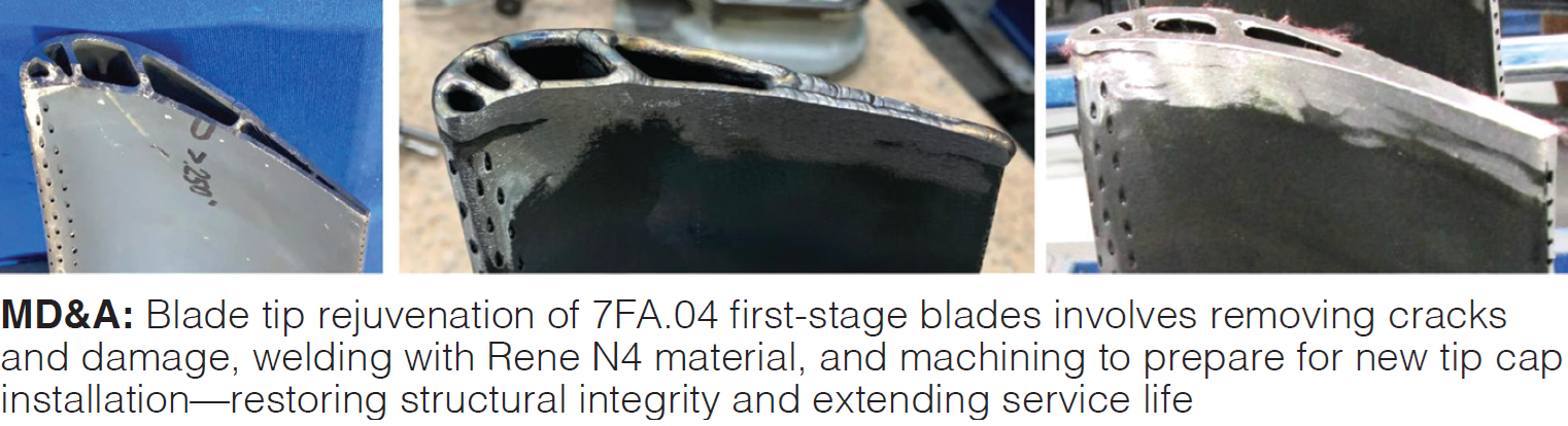
Gas turbine parts repair and solutions. Thanks to an EPRI-sponsored demo program, single crystal components are “fully repairable” using MD&A procedures, and you can expect performance improvements to boot. Jose Quinones’ slides focus on 7FA.04 shroud tiles, with a two-layer abradable coating; row 1 blade tip restoration, inspection, and coating; 1st and 2nd stage nozzles; and row three blades (with no internal cooling), for which a repair process is said to be “elusive.” MD&A uses a high-cobalt alloy for blade restoration instead of Inconel 650.
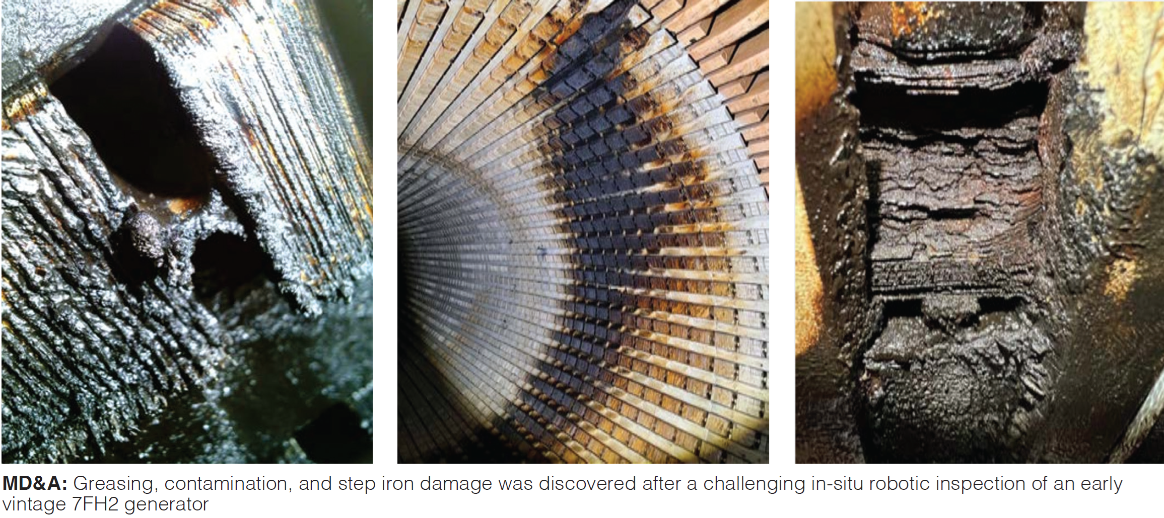
7FH2 step iron liberation. Early 7FH2 generators have an iron liberation defect acknowledged by the OEM (TIL2260) because the units were torqued to a lower threshold (2000 ft-lbs) than later units (3000 ft-lbs). Peaking duty leads to added thermal stresses and risk of liberation as units age.
This presentation by James Joyce covers the discovery of step iron liberation during a challenging in-situ robotic inspection of a 1996-vintage unit (204.5 kVA), an assessment of repair options, and the subsequent partial restacking and full stator rewind.
Specifically, MD&A:
- Stripped existing windings and removed the core compression flange (CCF) and three full packs of core iron
- Cleaned all stator components of ferrous material deposited during operation
- Replaced core iron and compressed the CCF to the recommended threshold
- Performed core loop test and thermally seasoned core to remove oil and ensure that the torque values were adhered to.
- Applied low-weeping epoxy to the newly installed core iron laminations
- Performed full stator rewind
MD&A recommends that lower serial number 7FH2 generators with high number of starts get a key bar torque test.
Control strategies for life extension. “Obsolescence is not the end,” says Vince Hilaire, and he’s not referring to a line from an apocalyptic film. Contrary to what the OEM may claim, you can recommission a legacy control system and upgrade it with MD&A’s IBECs integrated solution.
Recommissioning services include check/adjust power supplies, verify I/O is properly connected, investigate and clear nuisance alarms, conduct loop checks, calibrate instruments, and consult on unit operations. IBECs features native drivers and open-source protocols, alarming and pattern recognition, time synchronization, redundancy and change replication, sequence of events recorder, high-speed trending and data historian, and remote access and monitoring.
Turbine
Interpreting borescope reports
TG Advisors LLC
Jason Neville
Why conduct Borescope Inspections (BSI)? According to Neville, BSIs allow you to trend turbine wear and specific issues for better risk management. They lead to evidence-based, educated decisions on machine issues, replacement hardware, TIL compliance, repair resources, and downtime. In addition to regular intervals (minimum annually), BSIs should be conducted after abnormal engine behavior, combustion spread events, vibration step changes, wheel space and exhaust temperature shifts, precommissioning, and post overhaul. Specific slides offer handy lists of inspection areas by section – compressor inlet, compressor, combustor, turbine, and exhaust.
GE 7F DLN 2.6 fuel nozzles
APG
Jeremy Clifton
Slides review fuel nozzle basics (parts descriptions) and inspection and repair processes. Emphasis is placed on rebuilding bellows for pre-mix nozzles and fuel distribution valves, and new stiffener design, featuring three centering slotted spaces instead of two, for liquid fuel cartridges.
Engine-ready advanced TBC coatings for IGTs
Honeywell/Liburdi
Josh Smelzer
Smelzer hones in on two versions of a low-k (thermal conductivity) thermal barrier coating (TBC) now under long-term testing. The dense vertically cracked (DVC) version is for rotating parts, a porous version for stationary parts. These TBCs are said to be 10-30% lower in thermal conductivity than the industry standard 7YSZ and phase-stable to 3100F, 500 deg F higher than standard.
Slides include microstructure photos, thermal k data, cyclic testing results, and bond cap tensile strength values. Long-term testing includes four years in the field, shop, and lab. Phase 2, from 2022-2026, comprises parts installed in a commercial 7FA.03 GT with flared compressor, and steam-injected combustor operating at 2350F. Photos of early results are included.
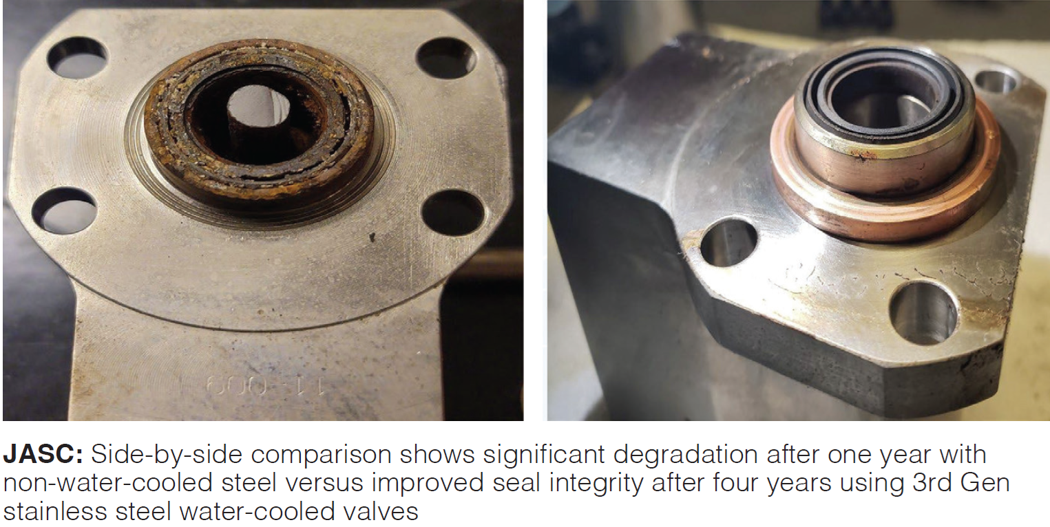
Understanding the impact of BOP equipment on liquid fuel system reliability
JASC
Schuyler McElrath (RIP)
The esteemed McElrath, who passed away early in the year, reviewed JASC’s 3rd generation fuel system improvements (Fig 2) which seek to maintain seal integrity and prevent leakage in the liquid fuel, purge air, and water injection piping and valves. Included in this iteration are heat sink clamps on fuel lines in the turbine compartment and stainless-steel valve housings.
GTOP4 and FlameSheet™: alternatives to advanced OEM designs
PSM
Kevin Powell, Katie Koch, Andrew Ascala
Results from the first GTOP4.1 upgrade installation should be available this year. PSM says it is AGP (advanced gas path)-compatible, includes more durable materials than the OEM’s, and has better seals. Presentation covered redesign and upgrade details for R1 nozzle technology, 1st stage buckets, R1 shroud blocks, R2 nozzles, R2 buckets, and R3 buckets. Multiple sets of these parts had already been sold at conference time.
Also covered was Flamesheet™, PSM’s homegrown combustor technology now featuring the unique dual recirculation zones and incorporating micro-mixing technology. GenVII Flamesheet, which addresses the Gen VI distress modes revealed in early operation (discussed in detail), has been applied across the F- and E-class turbines, with frame 5 and 6B in development. Ten FA units with Gen VI Flamesheet were in operation at conference time.
Generator
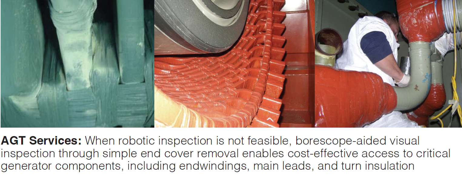
Generator robotic inspection – benefits, challenges and contingencies
AGT Services
Jamie Clark
Industry resources for major work on the 3000+ generators built since 1995 are constrained. Clark gives scheduling tips for planning major and minor outages and inspections, especially how far in advance to lock in resources since repair durations can take from one to seven weeks depending on scope. Clark reminds users that the catch phrase, “robotic inspection,” refers to many different robotic devices and generators with different core lengths, air gaps, wedge depths, etc.
Generator stator end-winding vibration operating deflection shape confirms global resonance
IRIS Power-Qualitrol
Aaron Doyle
For a 72.25-MW 2-pole generator, modal analysis and bump test identified an elliptical mode shape of concern near 2x line frequency, which was confirmed by installing fiberoptic accelerometers to monitor end-winding vibration.
Generator monitoring for safety, efficiency, and risk mitigation for now and beyond
Environment One Corp
Christopher Breslin
Machine age increases risk and condition monitoring helps manage risk. Company’s GCM-X core monitor, described in detail, immediately detects generator overheat and insulation degradation by sensing particles in the hydrogen coolant stream, verifying their presence, collecting them, and triggering alarms for operators.
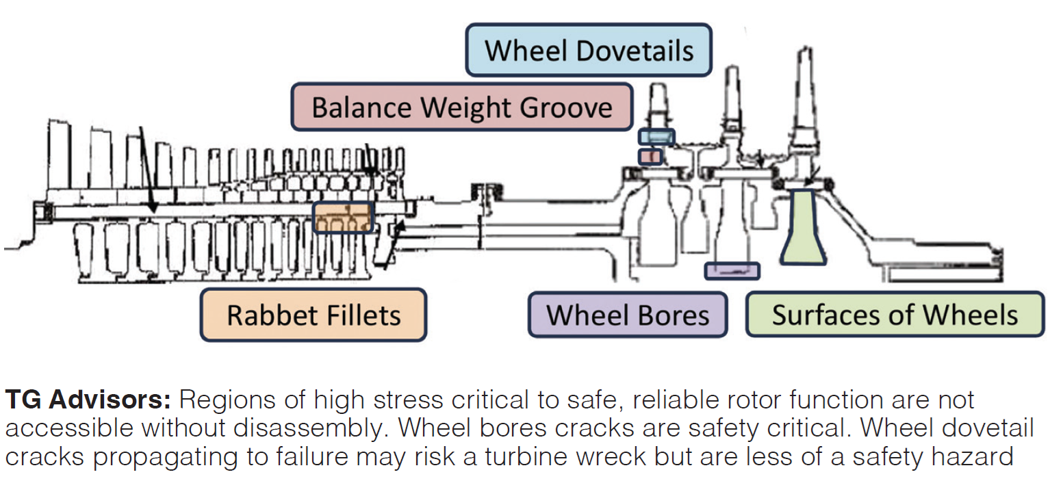
Rotors
Rotor end of life
TG Advisors
David Butz
GER3620 and TIL1576 state that 7F rotors pose an elevated risk of failure at 144K FFH (factored fired hours) and/or 5000 FFS (factored fired starts). However, this doesn’t mean they are unusable. Slides present an overview of the F-class rotor (reminding that there are three different sizes) and the key areas of interest at end of life (Fig 4). One notable slide states the good, bad, and ugly of Inconel 706 (primary rotor material); another lists common stator and field issues with the 7FH2 rotor. Options compared include continue to use as is, replace with a refurbished or used rotor with remaining life, or replace with new.
Rotor life extension by design
EthosEnergy
Jeff Schleis
After intro material on market conditions leading to greater machine cycling, TIL1576, and industry solutions, focus of Schleis’s slides is enhancing rotor design, (1) by selecting replacement alloys to match actual stress data and (2) through minor geometry alterations which are still fully compatible with original parts. Dubbed the Phoenix, it is a certified new rotor at reduced capex. One Phoenix and one new rotor were installed at a plant in March 2024 with (at conference time) no issues for either.
GT rotor life risk assessment with cycling and load swinging in a renewable energy support function
Structural Integrity Associates
Matthew Ferslew
Over time, frequent starts and stops create mechanical (rotational speed) and thermal gradient stresses which then can initiate and propagate low cycle fatigue (LCF) cracks; load swings propagate cracks beyond danger thresholds. The key to being able to swing load safely is frequent inspections inside and outside the rotor using techniques such as magnified borescope, surface penetrant (FPI/FPT), ulstrasonics, and eddy current, depending on the alloy, location features, etc, especially in the highest risk areas.
During the Q&A, Ferslew highlighted the flat slot bottoms of rotors in production before 2004, after which the OEM switched to round slot bottoms. The flat variety is a safety issue but is not generally included during normal inspections. Compressor stages 16 and 17 are areas of particular interest.
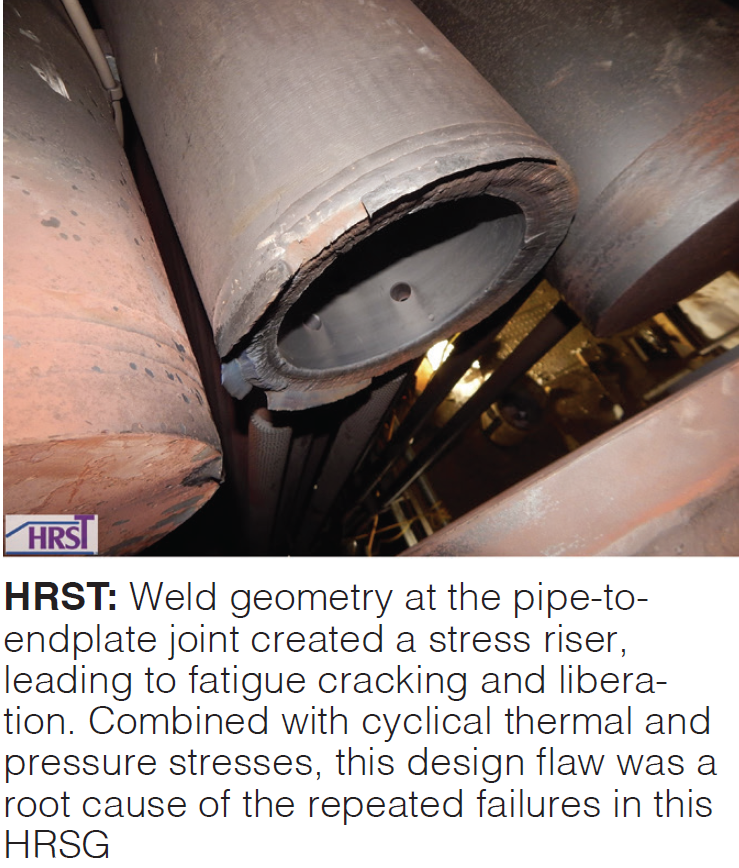
HRSG
Effects of GT operational changes on HRSG pressure components – case studies
HRST Inc
Souvan Chakirov
After a review of industry challenges affecting HRSG O&M (especially aging of the fleet since the 2000-2004 bubble period), Chakirov outlines two case studies of component failures which all users should take note: high-pressure superheater end-plate failures and reheater manifold bowing.
After 2261 starts, an end plate in the subject unit failed and multiple fatigue cracking of end plates was discovered. Further investigation revealed that most of the end plates had ID initiated cracks. HRST developed and applied an innovative weld repair, then developed a new test method after another end plate failed. In all, 24 end plates were replaced at this plant.
In case 2, poor drainage of condensate and feedwater buildup caused bowing of the secondary reheater tube panel at multiple sites. HRST offers recommendations to address the drainage issue.
Balance of Plant
Turbine oil & life cycle management – developing a tactical plan to mitigate varnish
Shell Lubricant Solutions
Chris Knapp
Not all lube oils are equal even if they meet specs (Fig 6). Slides review basics of turbine oil formulation, varnish chemical composition, and oxidation of lube oil to varnish. The tactical plan includes selection of the oil, testing and analysis, managing baseline varnish potential, partial and full oil changeout, and managing increasing vanish potential.
Key tests include MPC (measures levels of varnish components, TAN (acid number -indicates varnish buildup), RUER (antioxidant level remaining), and RPVOT (remaining life with respect to oxidation potential).
Air filtration and extreme weather
Donaldson Filtration Solutions
Bob Reinhardt
The extremes under scrutiny here are snow and ice, wildfire smoke, extreme heat, and high humidity and coastal locations. Bulleted topics included are pulse system, snow hoods, heat tracing and vanes, success of HEPA filters with smoke, watertightness, and preventive maintenance, including pulse system checks, pre-filter changeout, evaporator cooler tuning, and hood treatments.
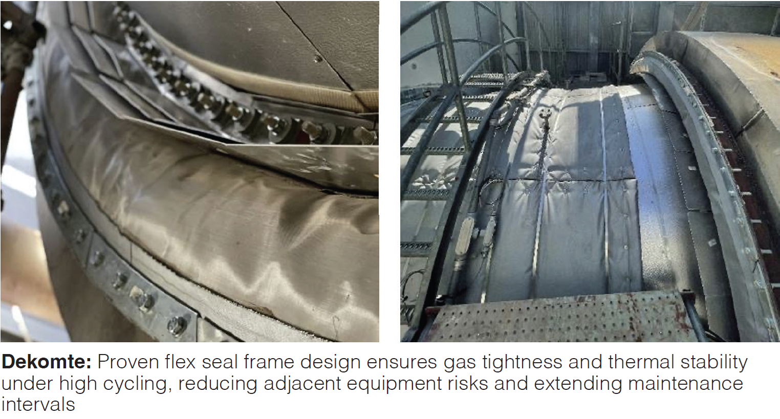
Flex seal solution for high cycling and gas tightness
Dekomte
Jake Waterhouse
Do you consider your flex seals a consumable or a long-term solution? Slides argue that, given potential issues with the OEM’s original seals, you have three options: A standard OEM solution (three-year life), an advanced seal (six-year life), or Dekomte’s 15-year solution. Details for five applications (GT inlet, GT exhaust, HRSG inlet, HRSG outlet, and boiler penetration seals) and case studies are provided.
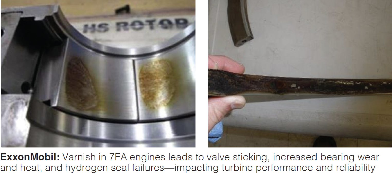
Turbine overhaul to overhaul reliability
ExxonMobil
James Hannon
Slides cover Mobil’s turbine oil triage strategy to mitigate varnish, including basics on varnish chemistry and formation, varnish tests and limits, and oil replacement options. Consequences of varnish are sticking valves, wear and higher than desired temperatures on bearings, and H2 seal failure. Details on company’s Solvancer™ and System Cleaner products and its proprietary valve varnish rig test are provided. Data from the rig are “more relevant than glassware tests.”
The role of the owner’s engineer in outages
Gulf Turbine Services
Joe Mitchell
Benefits of owner’s engineers (O/E) extend beyond their traditional role in project oversight, says Mitchell. They can assist in pre-outage planning activities, augment on-site staff, and plug knowledge gaps when experienced staff members retire or leave. Examples cited include a flange-to-flange upgrade of a 7FA.02 to .03, flange to flange upgrade of a 7FA.05, diverter damper overhaul, project management of a steam turbine major outage, and O/E for a 2x7FA.02 and D11 steam turbine triple major.
Controls
Performance evaluation and instrument calibration
AP4
John Downing
Downing reminded the audience, essentially, to sweat the small stuff which can often lead to unit trips, i.e., the instruments, sensors, valves, transducers, transmitters, and all of the associated components which comprise the control system. The GT is a finely-tuned machine and out-of-calibration instruments degrade performance. Thermocouples start to drift with operating time. For example, there are 12 data points used directly to raise and lower load, but there are 42 other data points associated with them. The control scheme is based on critical reference parameters and constants which need to be accurate.
Transducers in the control loops are often located in areas susceptible to vibration and high temperatures. Older machines tend to have old cables whose insulation may have deteriorated or are interfering with electrical equipment. Lots of issues have surfaced with compressor bleed valves and inlet bleed heat, inlet guide vanes, fuel gas valves, cooling and sealing air, and other subsystems.
Embedded in Downing’s delivery is a plea: “Do your performance checks, make sure instruments are not neglected during outages, pay attention to cybersecurity threats, and stay updated on what your insurance carrier is requiring (such as compressor discharge pressure transducers to detect stall).
Best Gas Turbine in the World – with “issues”
At the 2024 7F Users Group Conference, held shortly after GE Power officially transitioned to GE Vernova (GEV), users and GEV representatives gathered to explore challenges, share updates, and discuss the future of the 7F gas turbine fleet.
With “ver” symbolizing green and “nova” meaning new, GEV introduced its refreshed identity and recommitted to supporting plant-level performance. Yet, as many attendees noted, execution in the field still needs to catch up with the promise of innovation.
GEV Day opened with a candid acknowledgment from a 7F User Board member: “It’s the best gas turbine in the world…but it has issues.”
That sentiment encapsulated the day’s discourse—recognition of a strong foundation tempered by a call for better reliability, communication, and support.
User-identified priorities
During a closed-door session the previous day, plant operators and engineers outlined their top five concerns:
- Component repair quality
- Field services performance
- Aging fleet units, particularly from 1997–2004
- Proliferation of TILs for new technologies like DLN 2.6+ and 7FA.05
- Supply chain limitations
GEV addressed each of these areas throughout its presentations, aiming to provide clarity and highlight tangible improvements. As GEV presentation materials are not available with the rest of the 7F conference content, you’ll have to request details from your GE site representatives or access through your customer portal.
Focus areas
After a brief corporate review, GEV reps listed some of the accomplishments of the previous year in the areas of technology development, corporate culture, outage services, and safety. GEV’s “Live Outage” approach had “pockets with fantastic outcomes, and pockets which were not,” according to one specialist.
The top drivers of unreliability in the 950+ machine fleet worldwide are, in this order, combustion system, cooling and extraction air, fuel system, controls, and exhaust system. Users with the 2.6+ combustion system are “sharing reliability improvements.” Sub-components mentioned specifically as affecting reliability stats are flame detectors for combustion, compressor bleed valves for extraction air, gas control and safety relief valves in the fuel system, and exhaust thermocouples (TC) and communication links in the controls.
The company has been making large new investments in new rotor manufacturing and rotor repair capability to the tune of over $350M.
Quality metrics
The presenter on quality metrics acknowledged that GEV needs to get better. In field services, crew quality and planning were listed as the top issues, with parts availability, field services scheduling, and work quality rounding out the top five.
The company is “pursuing zero defects relentlessly.” Some of the new programs supporting the goal include:
- Stop work actions to address defects – 50% increase in stop-work situations to identify and address systemic sources of defects
- Strategic focus on third party parts – the designated supplier quality program (DSQP) is in place at over 100 suppliers and a Parts Failure Modes and Effects Analysis (PFMEA) has been “implemented across the top 40 risk areas.” The DSQP rep resides at the supplier site but is trained by GEV.
The goal is to shift from reactive to preventive with respect to defects in part because “we’ve been humbled regarding quality.” Part of that humbling was increased supplier quality incidents and nearly two dozen new Technical Information Letters (TIL) released since the 2023 conference.
RCAs and recent TILs. The root cause analysis (RCA) process at GEV follows the “Eight disciplines” methodology for identifying, solving, and eliminating problems. Presenters stressed that RCAs take time, and GEV is trying to improve on this “top user concern” with greater visibility into the process. Bi-annual webinars have been instituted to address RCAs and users can now access an “RCA Fleet Dashboard” with the status of each item. Users responded positively to these new initiatives.
In a field services update, the presenter mentioned GEV’s field engineering program to “establish a pipeline for recruiting and training entry-level workers,” recognizing that “it is difficult to get new people.” The 100 “live outage” events last year are characterized by five key pillars – core crews, simplified procedures, sequencing, material flow, and tooling.
Site workers are supported by a remote outage support team (ROS), comprising 35 seasoned experts (level 3 and 4) who answer questions and act as mentors for the field crew. Users also have access to the Power Answer Center (PAC) portal and can escalate matters with an Emergency Response (ER) case.
“What we have here…
…is a failure to communicate,” an oft-quoted line from the film Cool Hand Luke, which summed up much of the users’ frustrations during one open roundtable session.
One user complained that it often takes 3-4 days to get a response to an ER and another noted that “communication between the customer service lead (CSL) and the PAC died” on multiple occasions during an HGP. In a show of hands, more than half the room had experienced 2+ day delays for PAC responses. GEV responded by emphasizing proper escalation processes and noting their high case volume, though users expressed a clear desire for more responsive, plant-focused support.
Users also questioned or commented on: Getting consumables to the site for outages, why engineering responses were always associated with commercial aspects, difference in repair outcomes between Singapore shop and Greenville shop, inconsistent notification and publication of TILs, consistency in tools supplied to each site, retention of GEV technical assistants, difficulty getting shop representatives on the phone, and lead times of up to six months for critical spares.
GEV has responded by implementing a series of targeted initiatives to strengthen communication, reliability, and service quality for 7F users. These include refining ER escalation protocols through improved tagging, real-time monitoring, and automated alerts to ensure faster response times; assigning dedicated contacts from the Remote Outage Support team to improve continuity and execution during outages; and expediting the release and visibility of Technical Information Letters (TILs) through a new user portal with subscription-based notifications.
To enhance operational consistency, the OEM is developing regional inventory buffers for critical spare parts and tools and working closely with logistics partners to streamline delivery. A renewed investment in field service talent emphasizes training, mentorship, and retention to support long-term technical continuity at user sites.
Lastly, GEV is launching a comparative quality initiative across its repair centers to improve transparency, standardization, and user visibility into repair processes and outcomes. These improvements reflect a continued commitment to responsiveness, accountability, and collaborative progress.
Compressor, turbine
The following is a laundry list of topics and associated TILs covered in a session on compressor and turbine:
- Inlet guide vane (IGV) actuation system inspection (TIL2363-R1).
- S17 Gen V new shroud material (TIL1850-R3 but four others may be associated with it) – this is a long-lead time item and parts need to be procured at least a year in advance of installation. The parts enable migration to “next gen S17” and supercedes existing mechanically attached bushings a la Gen II, III, and IV.
- 03/04 RO compressor blade removal. Procedures were updated in 2024 based on RCA learnings.
- Wet-operation-related compressor fouling. Multiple 7F surge events are driven by fouling. Although high silica content in fogger system water was referenced, one user noted that they don’t have foggers and the fouling may stem from thermal barrier flaking during normal water washing.
- 04 stage 3 tip shroud distress (TIL2045 revision). Internal creep voids can initiate cracks and lead to shroud liberation. Affected parts and spares should be sent to a service center to receive cooling hole modifications. Parts not modified should undergo fluorescent penetrant inspection (FPI) every 4000 FFH until removal.
- 7F AGP flex S1N distress investigation. Trailing edge distress on S1N from oxidation and material loss has been observed on nozzles. RCA is in progress including material analysis. Users asked whether this was observed on multiple units, and answer was that it is considered unit-specific for now. Users also asked what the service profile was for the affected unit and the answer was ~15,000 FFH, with first observation at 11,000 FFH.
- AGP S1B tip oxidation and cracking distress. Pre-2019 vintage AGP tip repairs were based on Haynes 230 alloy for tip rebuilding but the material was shown to have worse oxidation resistance than the base alloy. GEV is rolling out and qualifying Haynes 233 for this repair. Additional cooling holes and tip trench may be necessary to reduce temperature.
These updates emphasize the need for timely guidance and consistent part upgrades to address fleet-wide challenges.
GEV’s vision for improved support, service, and a more resilient energy future was on full display. But as the sessions revealed, the user community remains focused on execution: timely communication, consistent quality, and dependable field service. By continuing to listen, adapt, and act on user feedback, GEV and the 7F fleet can evolve together to meet today’s demands and tomorrow’s opportunities. CCJ