Cooling towers, tank inspections, water chemistry, fire suppression, pump vibration…
With one exception, the CCUG Conference’s final-day presentations covered components that, as the first presenter joked about cooling towers, are in the “back 40,” whether that means physical location or in the minds of the staff. All the more reason to pay close attention, as these are still components which can impact financial, safety, and other performance factors.
Cooling-tower fans and drives. Batting leadoff was EPRI Technical Consultant Sam Korellis, who reviewed a cooling-tower (CT) fan-motor-drive and gearbox field evaluation program and its implications for CTs serving more than 800 units at around 300 powerplants.
CTs are equipped with multiple fans which start and stop depending on load and fans out of service. With many plants cycling more and more, these fans cycle on and off more as well. Since each draws auxiliary power, excess fans in operation penalize heat rate.
Korellis noted that the criterion to start or stop a fan is simple: If it allows an increase in net power. Starting a fan improves CT thermal performance and unit efficiency but draws additional power. Stopping a fan has the opposite effect.
Starting and stopping fans leads to gearbox failures. Gearboxes suffer failures at a 10% to 20% annual rate industry-wide, said Korellis, and they are costly. A new one costs about $30,000, plus about $5k in labor. They also require replacement power while out of service, can damage fan blades and other components, and can lead to oil contamination of the tower water.
Objective of the drive optimization project was to evaluate the start/speed regime under unit cycling. Operating wet-bulb temperatures ranged from 35F to 85F and steam-turbine load from 200 to 900 MW during the test program.
Three starting/speed regimes were tested: one-speed (on/off), a soft start (two-speed), and a variable frequency drive (VFD) capability. Under a variety of operating conditions (load, cold- water temperature, ambient temperature, fan speeds, number of fans in operation, etc), the VFD option offered the greatest net benefit in optimizing performance, and was similar in cost to the two-speed option, even if the latter is of a simpler design.
For the gearbox evaluation, project team purchased several new right-angle gearboxes, and installed and operated them in one CT, with additional monitoring capability, where they would be subject to identical operating conditions. Objective was an attempt to determine causes of frequent failures, effect of repeated start/stop cycles on gearbox reliability, and the relative reliabilities of gearboxes paired with the three start/speed regimes.
During the evaluation, four gearbox failures were experienced in one year. Elevated lube-oil failures also were noted. There were signs of low oil level, moisture contamination of oil, and high oil-pressure levels which caused vaporization and loss of oil. Oil temperatures greater than 200F were observed in the winter, and as high as 300F in the summer.
- Near-term modifications suggested by the results include the following:
- Upgrade to synthetic oil or higher-grade mineral oil.
- Check oil level and condition during warm operating months.
- Develop oil sampling and analysis to detect early degradation.
- Impose quality threshold levels for oil rejection and replacement.
- Continuously monitor gearbox temperature.
- Deploy real-time vibration monitoring sensors.
- Reduce dead air space around gearbox to promote better cooling.
Longer term and more involved/costly solutions include an automated lube-oil refill system and lube-oil sampling; addition of an external lube-oil filter and cooling system; or convert to a direct-drive system and eliminate the gearbox.
One attendee asked how to feed this knowledge into a design spec and Korellis said to add fins and/or a diverter to improve gearbox cooling, and add instrumentation to monitor temperature in the bottom of the gearbox. Another asked whether there was any difference in the performance of the soft-start versus VFD and the answer was “no.” A third asked about the oil sampling and the suggestion was to sample and analyze weekly, but cautioned that sampling apparatus could contaminate the water if the sampling tube leaks. Best to locate the sampling apparatus outside of the CT internals, he added.
Ammonia storage tanks. Batting second was an owner/operator presentation on aqueous ammonia (NH3) tank inspections. According to the governing standard API510, a “fitness for service” assessment should be conducted every 10 years (or half the remaining life calculated during the last inspection) for pressure tanks. The method results in a calculated remaining life, and typically the work is performed by a specialist contractor squad including an API specialist, NDE technicians (typically two), a confined-space entry team, standby rescue team, environmental contractor, scaffolders, and the ammonia supplier.
The owner/operator or plant should assign a point person to the project who coordinates with the contractors, prepares the tank documentation, gathers previous inspection reports, etc.
Since tank wash-down water must be disposed of as hazardous waste, an accurate estimate of the residual NH3 is necessary ahead of the work. You can expect between 2000 and 3000 gallons of RCRA-type waste which will have to be disposed of or stored onsite in a tanker. Plant should allow a full day for tank cleaning.
Once cleaned, the actual tank inspection is “pretty straightforward.” The NDE inspectors divide the tank surface into a grid and record thicknesses from ultrasonic transmitter (UT) readings at each location. Allow a second day for the inspection work. Plant staff should take the opportunity to service pressure relief valves, vacuum breakers, and other ancillaries, and leak- check the manway ports (easier for vertical tanks). Make sure to have on hand sufficient calibrated air monitors and extra ammonia sensors.
In response to questions, the presenter said that (1) they had not considered neutralizing aqueous NH3 prior to opening the tank, (2) the dump valve should be inspected and/or replaced at each inspection, and (3) the tanks are carbon steel, piping is stainless, and that iron can mix with the NH3.
Steam/water chemistry. Typically, you want your heavy hitters batting third or fourth. The third presentation, Steve Shulder (also of EPRI) addressing chemistry-related damage from flexible operations, belongs in the “heavy” category; most slides are laden with bullet points likely summarizing chapters of larger EPRI reports on water and steam chemistry issues. In fact, it’s almost impossible to condense the 45-slide deck into useful highlights, so review online at www.powerusers.org. It’s packed with good material for whoever is responsible for plant chemistry.
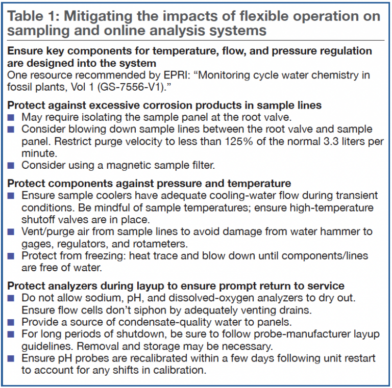
Two areas worth reviewing here, however, are (1) maintaining sampling and online analyzer systems and (2) plant layup and storage. Keeping the former in top working order is critical because, during operation, “you can’t control what you can’t see,” stressed Shulder.
Of course, online analyzer systems are also impacted by cycling operations and improper layup. Debris in the water/steam circuits can plug sample lines. Sample lines should be equipped with blowdown lines; lines and analyzers should have de-ionized water flowing through them so they don’t dry out. Other checklist items are shown in Table 1.


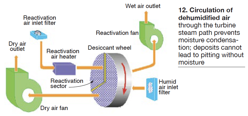
The table on best available techniques for layup and protection (Table 2) is a convenient guide organized by plant subsystems and components. Of note as well is a recently developed dehumidified-air system (Fig 12), proven at several combined-cycle plants in the south, which protects the turbine steam path from moisture condensation when offline for long periods. “Deposits cannot lead to pitting without moisture,” Shulder reminded the audience.


