Turbine Tip No. 10 from the PAL solutions library applies to General Electric package power plants (PPP), including the following: Model Series 5001, 6001, and 7001.
GE PPPs originally had Cardox CO2 fire protection (Fig 10-1) with individual bottles of suppressant connected in two systems—initial burst and sustained delivery—to three compartments: accessory base, combustion, and load gear and exhaust area. Frame 5 and 6 engines with reduction gears had two overhead “trap doors” that closed when the discharge occurred, to mitigate CO2 flow into the air-cooled generator from the load-gear compartment, thereby protecting the generator from contamination.

Each of the three compartments was equipped with color-coded temperature sensors indicating the ambient temperature allowed (Fig 10-2). If the temperature exceeded the setting in the tip sensor, the bottled suppressant would be discharged to extinguish the fire.
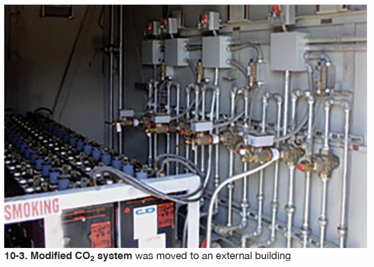
Location, location. Most GE gas turbines had fire protection systems installed inside their control cabs, taking valuable space away from plant operators. Owners typically didn’t like having the bottles so close to personnel, often moving them to an adjacent building (new or existing), thereby opening up space for a desk and chair. Fig 10-3 illustrates a system and batteries that were moved outside the control cab.

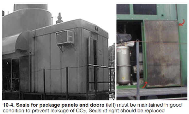
Enclosures for PPPs are supposed to be sealed to contain any fire that might occur. The goal is to entrap the fire and smother it with suppressant, extinguishing it as soon as possible. Thus, door and panel seals must be maintained in good condition (Fig 10-4). Insurance companies may require plant operators to “prove” the integrity of the sealing system.

Many insurance companies now are requesting that owners consider replacing antiquated fire protection systems. But before doing this, be aware of the following onsite considerations with the existing enclosures and fire sensing systems:
- Test the existing system for leaks—that is, deliberately discharge suppressant into the compartments to locate leaks, holes, rusted panels, etc. It is very likely that the door and panel seals have rotted, and the panels no longer fit properly to envelop and contain the compartment.
- Refer to the schematic piping diagrams for the tip ratings of compartment temperature sensors. Typical settings are as follows:
- Accessory compartment, 45FA-1 and 45FA-2 (200F nominal).
- Turbine combustion compartment, 45FT-1 and 45FT-2 (600F nominal).
- Load gear (exhaust plenum) compartment, 45FT-3 and 45FT-4 (500F nominal).
Caution: The CO2 fire protection system is passive. It remains in standby mode until a fire occurs in one of the compartments.
Personnel should “pin” the system whenever personnel are working in the area to prevent accidental discharge. If you think this can’t happen consider the following experience: During cranking checks on MS5001L fuel-regulator controls, a flexible coolant line feeding the diesel cranking engine burst, igniting the ethylene glycol. A flame ball roared through the accessory compartment and the CO2 system discharged to extinguish the fire. The technician was not injured seriously—thankfully—and no lost-time accident was recorded.


