By Jacob Bartol, HRST Inc
Final steam-temperature control in combined-cycle and cogeneration facilities can be a complex issue with many variables. An increasing number of F-Class HRSGs are experiencing problems stemming from any combination of the following: poor steam-temperature control, desuperheater overspray, leaking desuperheaters, blocked valves or nozzles, desuperheater control-valve “hunting,” etc.
Low-load operation is also an area of concern for many units because of the reduction in steam mass flow and simultaneous rise in GT exhaust gas temperature (with some GTs). In some HRSG designs, ones with unbalanced superheat and reheat surfaces, spraying to saturation (overspraying) at low loads is unavoidable.
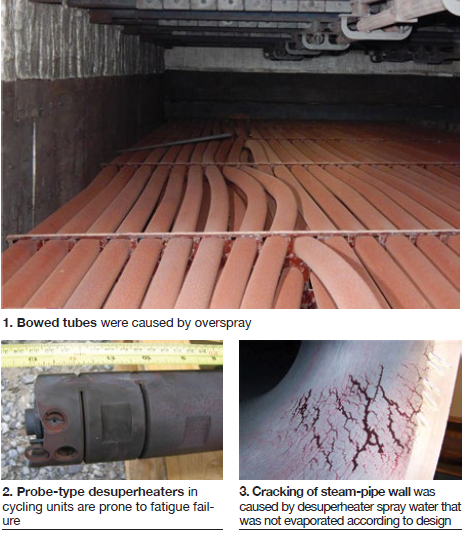
When the foregoing issues cannot be resolved by making adjustments to the control system, more sophisticated control philosophies can be deployed both to mitigate the problems and extend the lives of HRSG components, and to boost performance (power output). Poor steam-temperature control can damage downstream equipment (Fig 1) and increase plant heat rate.
Steam-temperature control functions have not changed much over the years; however, as the HRSG fleet ages some of these problems are starting to reveal premature failures and damage in some units (Fig 2). A typical control system uses the steam temperature at the turbine inlet, steam-system pressure, and steam temperature at the desuperheater outlet to calculate the required desuperheater cooling-water flow.
Although this control-system arrangement works to inherently supply steam at the required temperature, it does not have the ability to reduce other HRSG-related issues or to accommodate a cyclic load profile. Recall that the design basis for many combined-cycle plants originally was a baseload configuration.
It is also a very common practice for operators to lower steam-temperature set points to reduce the risks of high-temperature excursions and alarms. The intentions are good, but this then will increase attemperator spray-water flow, possibly causing overspray damage; plus, it also will negatively impact unit power production.
One of the benefits of most modern control systems (especially distributed control systems) is that a design can be implemented and tested prior to deployment as a controlling medium. Control philosophies can be implemented to precisely regulate steam temperature throughout a plant’s load profile.
Component impacts
Desuperheater overspray can lead to several problems in HRSG components and external steam piping. Typically when an overspray condition occurs the piping and components downstream of the spray nozzles are thermally quenched. This can cause ID-initiated cracking and potential premature failure of the components (Fig 3).
Desuperheater probes, liners, and steam piping are most susceptible to thermal quenching. Keep in mind that piping systems in the high-pressure superheat and reheat systems often is high-chrome steel, like P91, which can be expensive, challenging to repair, and have a long procurement lead time.
Superheater and reheater tube panels downstream of desuperheaters are also at risk of thermal shock damage. HRST often sees tubes that are bowed or deformed longitudinally, as shown in Fig 1. This damage stems from overspray in many situations.
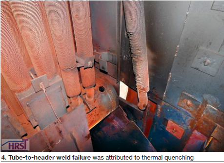
Excessive tube stress as a result of tube-to-tube temperature difference can put tube-to-header weld joints at greater risk of failure because of fatigue damage at these joints (Fig 4).
Issue mitigation
Although the desuperheater issues are not always completely resolved by controls-only solutions, control systems can help mitigate damage using basic thermodynamic calculations. These calculations perform an energy balance across the desuperheater using existing instrumentation and curve-fit data in the DCS to control spray-water flow rates more accurately.
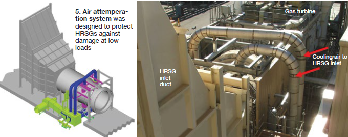
The system can be built into existing control functions and act as a bias signal to alleviate excessive spray flow to a certain extent. Alternatives include the QuenchMaster® air injection system to help mitigate this and other steam temperature control issues related to overspray at low loads (Fig 5).
Desuperheater control- and block-valve arrangements that allow water to leak into the system can also cause thermal quenching of the associated components downstream of the desuperheater. Many control valves are not designed to operate in the lower range (<5%) of their travel because of turndown constraints as damage to the valve trim can occur.
Valve manufacturers typically suggest a block-valve arrangement upstream of the spray-water control valve to prevent this condition. HRST recommends a block-valve arrangement and a control philosophy that closes the block valve when the spray-water control valve position is <5% open. DCS alarm signals can be implemented to inform when a system is not operating optimally and is at risk of damage.
One of the most basic alarms is a comparison of calculated steam saturation temperature to actual steam temperature in a desuperheater system. This alarm ensures the process is not spraying down to saturation temperatures. HRST recommends desuperheaters maintain a minimum of 30 to 50 deg F of superheat to prevent thermal quenching of downstream components. A function similar to this also can be used to detect a leaking desuperheater spray circuit that allows water flow into the system with no spray-water demand.
Initial design practices
Many of these issues are a direct result of control systems designed only for temperature control, or a plant originally designed as a baseload facility and now cycling. Many HRSG-related components often are overlooked during the design phase of a project, with other plant equipment believed “more important.” In some cases, the designer is not as familiar with the impacts of other equipment (gas turbines, in particular) on the HRSG. CCJ


