
2024 501F BEST PRACTICES AWARDS: BEST OF THE BEST
- Anti-icing system prevents snow-related derates, outages
- The road to reliable ultrafiltration
- Experience upgrading Siemens’ T3000 V9.2
CPV Valley Energy Center
Owned by CPV/Diamond Generating Corp
Managed by Competitive Power Ventures
Operated by DGC Operations LLC
680 MW, gas-fired 2 × 1 SGT6-5000-powered combined cycle, located in Middletown, NY
Plant manager: Michael Baier
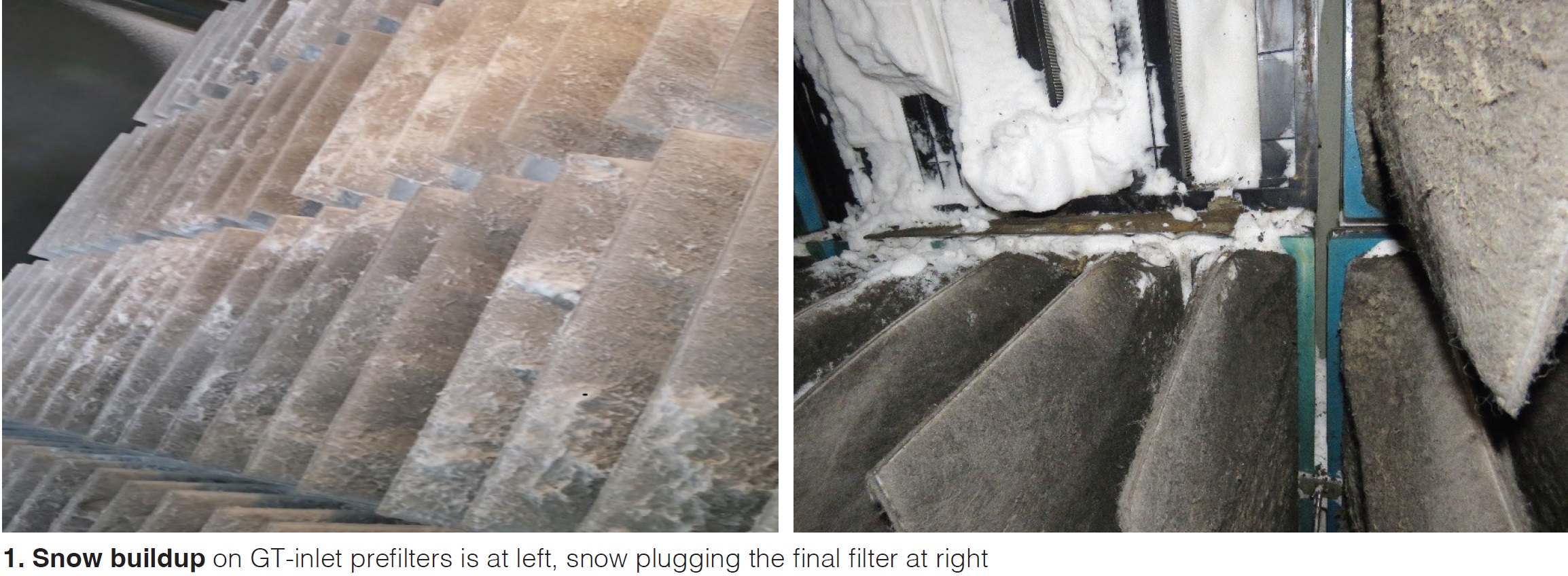
Challenge. Since commissioning, during winter weather events, the gas turbines would have to derate and/or take a forced outage because of snow clogging the compressor-inlet prefilters (Fig 1). The problem persisted with an upgraded filter design, replacing the flat, box-style filters with a reverse pocket design. Through experience, the site developed a winter-storm protocol to derate the plant when the inlet-filter differential pressure (DP) started to rise. A combination of plant staff and contractor personnel were made available to physically remove the snow from the filters during weather events. Even with the proactive measures in place, at least one of the GTs generally would be forced offline.
Solution. Valley Energy Center and Competitive Power Ventures personnel worked with PSM to engineer and implement an anti-icing system that would tee off the existing compressor inlet-bleed-heat (IBH) system. The system tees into the IBH piping upstream of the OEM’s block valve inside the gas-turbine package (Fig 2). The anti-icing system, when in service, directs air from the GT’s compressor to the front of its inlet prefilters via an array of patented stainless-steel nozzles.
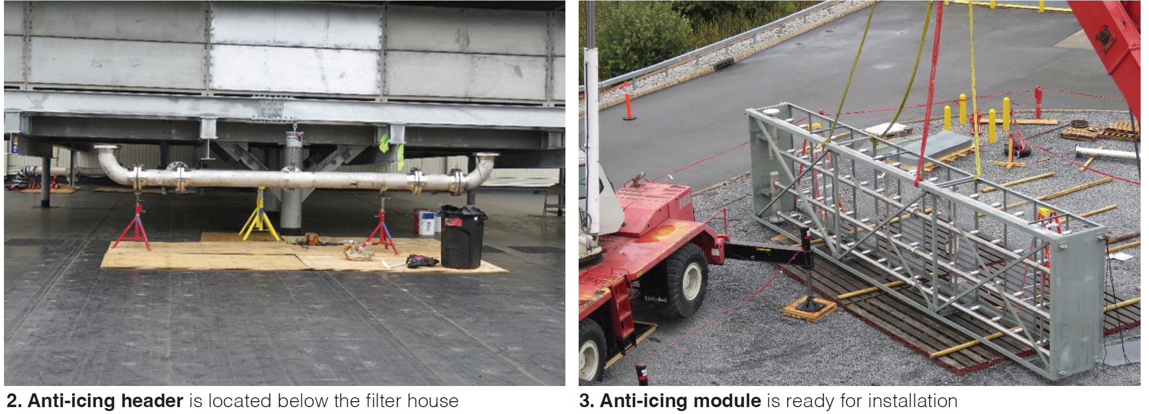
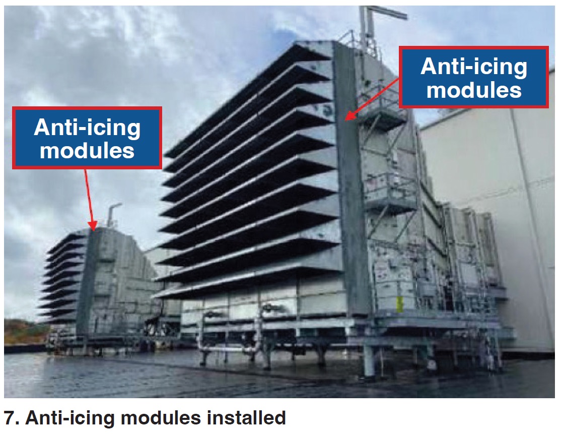
The nozzles include silencing media and perforations to disperse the air, thereby creating a curtain of hot air that melts most of the snow ahead of the prefilters. The nozzles are threaded to stainless-steel piping inside carbon-steel modules bolted to the face of the existing inlet structure (Fig 3).
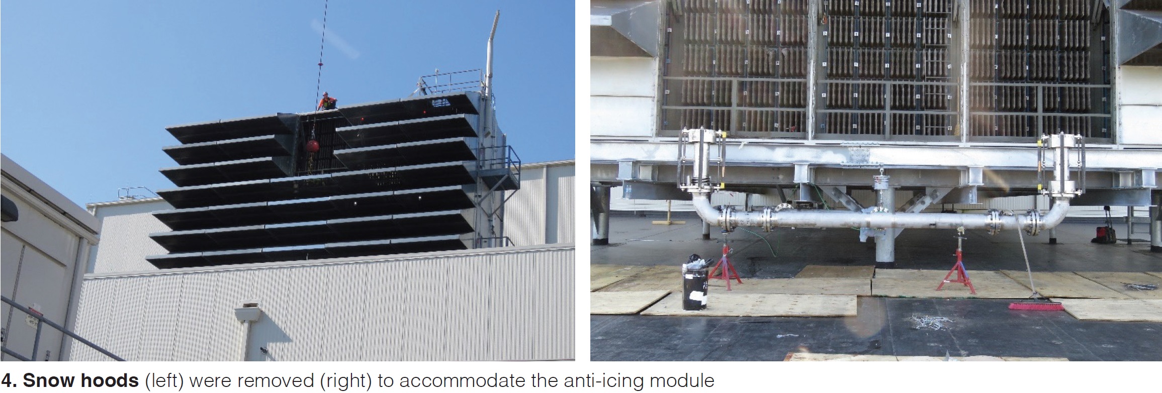
Structural steel was added to support addition of the modules. In total, five 9 × 45-ft modules were added to each inlet house (Fig 4). The modules were flown to the roof using a crane (Fig 5) and then bolted in place before removing the modules from the crane hook. The modules contained the stainless-steel piping that the nozzles were threaded into.
Some of the piping and valves were installed while the unit was online, the remainder concurrently with HGP inspections on both GTs. Before the outage, the first revision of the logic for the anti-icing systems was developed and installed. Because the facility also was undergoing a DCS upgrade during the HGP outage, PSM, CPV Valley, and the DCS OEM worked to add the logic to the DCS version that was going to be uploaded during the outage.
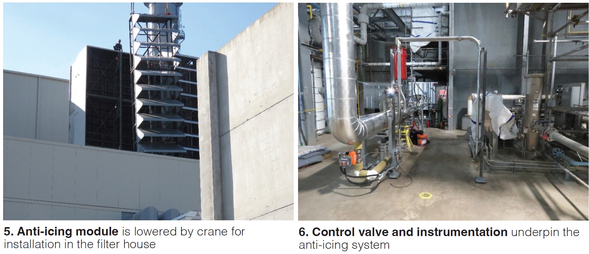
Additionally, during the outage, a PSM subcontractor installed all the instrumentation and ran all the control cables for the instrumentation and valves to the I/O cabinets (Fig 6). CPV Valley personnel made the final connections in the I/O cabinet. After all connections were made, loop checks were performed to verify all the wires were landed to the correct points.
Upon mechanical completion of the anti-icing systems, one gas turbine was brought to full speed/no load to check for leaks from all pipe flanges. After a satisfactory leak check, all the flanges were insulated. Several weeks after returning to service, PSM came back to run a functional test of the anti-icing systems on both GTs, tune the control valves, and set protective limits using temperature as a parameter.
For the test, a temporary thermocouple array was installed in each GT’s filter house to monitor the temperature at the inlet filters. After initial testing, other modifications were made to the logic for additional GT protection. For personnel safety, signage was added to the filter-house doors on both units warning not to enter without being on a LOTO; and the doors were padlocked shut as an additional measure.
Before the first use of the anti-icing systems, a draft operating procedure was created and reviewed with operations personnel so that they were familiar with the permissives required to place the system in service and what parameters to monitor while the system is operating. During the winter, as site personnel became familiar with how the system operated, several revisions were made to the procedure, and parameters were adjusted in the logic.
Results. Despite the 2023/2024 winter being mild in southern New York, the new anti-icing system was placed into service six times—all successful. Prior to first use, temporary cameras were staged and focused on the lowest section of the inlet prefilters on both units to allow remote monitoring of the filter condition (Fig 7).
For the first storm of the 2023/2024 winter, Jan 6-7, 2024, additional staff was brought to site as standby support. Plus, the plant engineer was onsite to assist in the event there were any issues with the logic that prevented the anti-icing systems from going into service.
The anti-icing system performed as expected during the first storm, with no operational issues other than the anticipated loss in megawatts. Based on trending and operator observations, the amount of snow clogging the inlet filters was minimal compared with previous storms of similar magnitude. No entry into the inlet house was necessary.
Comparing GT performance to a snow event on Feb 27-28, 2023 that caused one unit to shut down, the plant was able to operate with greater availability during the first 2024 storm because of the anti-icing systems. Review of the DCS historian data (Fig 8) captured during the 2023 storm revealed that inlet-filter DP had climbed to more than 2 in. H2O on both units while limiting plant output to a low of approximately 200 MW.
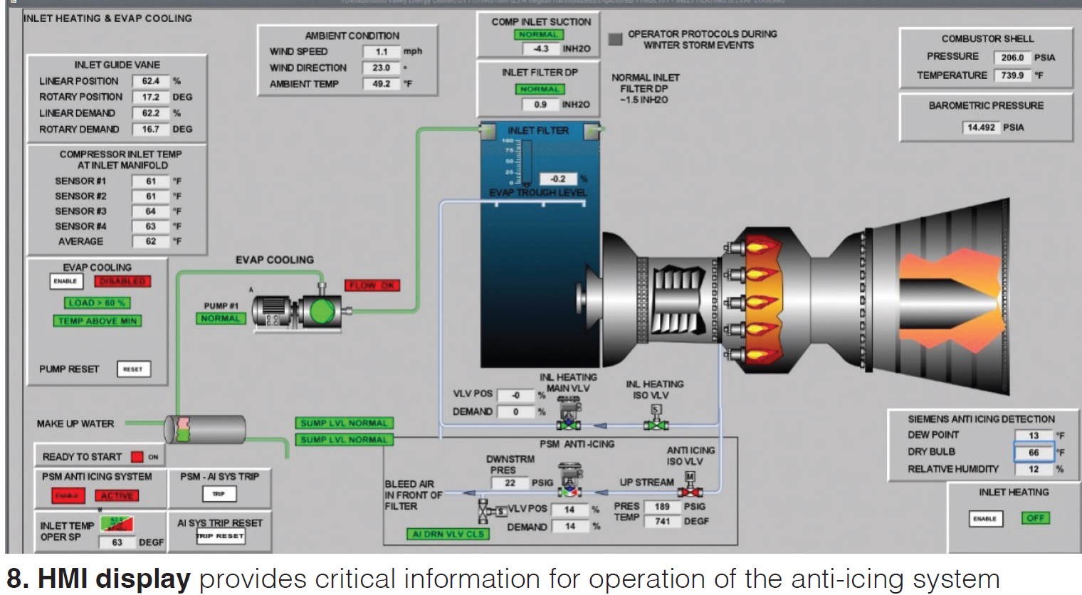
During the first event in 2024, with the anti-icing systems in service, the DPs for both GT’s inlet filters stayed around 1.3 in. H2O (with the exception of a short spike to 1.8 in. on one unit). Plant output stayed above 520 MW for the duration.
During the 2024 storm, duct firing was not permitted while operating the anti-icing system because HRST Inc was performing an analysis to determine if there was a risk of damaging HRSG components downstream of the firing duct. Result of that analysis: The site could operate the anti-icing system without limitation; however, at the time this entry was submitted for Best Practices judging, no tests had been performed because of warm ambient temperatures.
Project participants:
Michael Baier, plant manager
McKenzie Slauenwhite, plant engineer
Thomas Viertel, maintenance manager
Dave Engleman, operations manager
Bob Arraiz, lead IC&E technician
Daniel DeVito, IC&E technician


