By Scott A Wambeke, PE, HRST Inc
Problems with desuperheaters—attemperators if you prefer—have become more prevalent in recent years. The incident rate roughly tracks the industry’s increased reliance on combined-cycle units with F-class gas turbines (GTs) and large heat-recovery steam generators (HRSGs) operating at high pressures and temperatures. The majority of these units, designed for base-load merchant service, have been relegated to cycling duty because of changes in market conditions. The new operating regime is one reason for some of the problems.
HRSG designs vary greatly and how best to minimize your risk with respect to desuperheater operation likely requires investigation. Some of this work can be done by the plant staff, but, in many cases, a detailed study to analyze performance across a wide range of operating conditions is required.
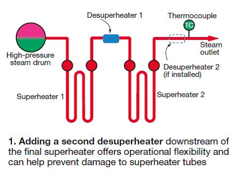
Experience indicates that the solution to a given problem may be as simple as installing tube baffling, moving a nozzle or a thermocouple, or adding a drip leg; or as complex as adding a desuperheater (Fig 1) or removing some heat-transfer surface. The use of “temperature matching”—a term that describes GT software modifications designed to restrict the exhaust-temperature ramp during startup loading—in combined-cycle plants reduces the potential for such damage, but is no panacea.

Desuperheater problems can occur during startup, transients, and at steady-load operation. Some, such as overspray, can cause serious damage with a single occurrence; others just chip away at fatigue life and/or efficiency. Here are thumbnail sketches of a few common problems:Closely monitor desuperheater operation
Startup overspray, possible in any HRSG, occurs most often in units behind an F-class GT because turbine exhaust temperature exceeds 900F much earlier in the startup routine than with older machines. Here’s what happens: Soon after turbine startup, the HRSG begins producing steam and the temperature of the steam in the superheaters ramps quickly, approaching the exhaust temperature. The desuperheater sprays heavily to maintain a steam outlet temperature that matches steamturbine requirements—typically 1050F.
In some instances, the spray can be so heavy that “wet” steam is sent to the superheater. The quenching effect of the moisture can initiate cracking in the area of some tube-to-header joints and/or permanent distortion of some superheater tubes (sidebar).
Another possible solution is to install a second desuperheater downstream of the final superheater section (Fig 1) to reduce the amount of spray injected by the primary desuperheater.
SIDEBAR: How superheater, reheater tubes fail
Understanding how a poorly designed, installed, and/or operated desuperheater can cause tube failures in the superheater or reheater of your heat-recovery steam generator (HRSG) is made simple by following—in sequence—the four sketches here.
The first illustration shows the key elements of a typical desuperheater used in combined-cycle service. Note the block valve, which should be installed to ensure tight shutoff when the desuperheater is not in service. The Class IV-shutoff control valves typically specified for HRSGs intended for base-load application often wear in the cycling service common today and may not close completely when the desuperheater is “off.”
A properly designed desuperheater has atomizer nozzles that (1) ensure against the formation of droplets too large for complete vaporization ahead of the superheater and/or reheater headers, and (2) produce a spray pattern that fills the pipe uniformly, as shown, to minimize the potential for thermal gradients. Important to remember is that your desuperheater should be installed in a straight section of pipe two to eight pipe diameters in length upstream of the nozzle assembly, 12 to 20 diameters downstream of it.
 |
Sketch B illustrates normal operation. Steam flowing into the upper header of the superheater or reheater contains at least 50 deg F of superheat. (The optimum amount of superheat for your facility is recommended by the HRSG manufacturer.) Observe that the tubes are of the same length and that turbine exhaust-gas flow and temperature are uniform across the tube bank.
In the next illustration, steam flowing into the inlet header is at or near the saturation temperature. This operating condition can result in “wet” steam entering the downstream superheater or reheater and quench-cooling the inner surfaces. The tubes try to shrink, but tube-to-header joints at the top and bottom won’t allow them to do so. Result is that they “yield,” sometimes so severely that cracks occur in the joint area (see photo and sketch in “Root-cause analysis of HRSG tube failures key to confidence in operational reliability,”
Tubes that yield, but don’t fail, are permanently longer after quenching and take on the appearance of spaghetti (Sketch D) when the desuperheater transient is corrected and operation returns to normal.
High desuperheater demand at low loads.
The exhaust temperature for a GT operating at low load can be the same or higher than that for a unit at rated output. For example, exhaust from an Fclass turbine can be nearly 1200F with the unit at 50 MW during startup. Result is that steam absorbs more heat in the superheater than at other conditions, and possibly more than was intended by the OEM (original equipment manufacturer). To compensate, the desuperheater may have to spray to near saturation conditions to maintain the desired steam outlet temperature. The increased demand for desuperheater spray can result in a “wet” steam scenario similar to that described for the startup overspray problem above.
However, even if the high rate of desuperheater spray does not reduce steam temperature to near saturation, producing a high percentage of the steam from spray water can compromise steam purity so important to the steam turbine. A rule of thumb is that if more than 8% of the steam at the superheater outlet comes from spray water your plant may be at risk with regard to steam purity.
Reheat bypass/conditioning valve overspray. If reheaters are not designed to run dry through the startup sequence, it’s necessary to reduce the pressure and temperature of high-pressure steam and rout it through the reheaters. The conditioning system (often a large pressure-reducing valve with integral spray nozzle near the valveoutlet) is susceptible to overspraying and sending wet steam to the cold reheat section of the HRSG.
Leaking desuperheater.Operators sometimes are not aware that they are desuperheating almost all the time. Leakage is lost efficiency during regular operation and can be damaging in other ways—such as quench cooling of select tubes, piping, or headers and/or the buildup of water in piping that can cause water hammer at the next startup.
Early in startup, during shutdown, or in operating modes that do not normally require spray actuation, water flow to the desuperheater should be at zero. If it is not, the cause most often is the control valve, which normally is specified with Class IV shutoff—marginal for tight shutoff against a large pressure differential. In brief, these valves are not designed for isolation service and almost certainly will leak at some point in their lifetime. This is why the overwhelming majority plants have block valves upstream of their control valves. For plants with multiple HRSGs supplying a common header that serves the steam turbine, ASME B31.1 requires block valves with actuators. Use them.
Failed desuperheater nozzle assembly.Desuperheater nozzle assemblies have failed at HRSGs in both cycling and base-load service. When nozzles fail, spray water typically enters the pipe perpendicular to steam flow and is not atomized for effective mixing and rapid evaporation.
Be aware that the desuperheater is prone to cycling independently of the HRSG under certain conditions. For example, if the amount of superheater or reheater surface is “just right” to achieve the desired steam outlet temperature with little or no spray water flow, the desuperheater may turn on and off continuously when plant output is constant. Likewise, if the desuperheater control loop is too tightly tuned—that is, trying to control temperature within 2 deg F with little or no deadband—the valve may be prone to hunting.
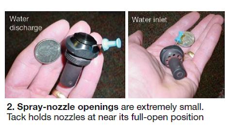
Plugged nozzles. Spray-nozzle openings are extremely small (Fig 2) to ensure effective atomization of the spray water. Tack in photo is holding the nozzle at near its full-open position. What this means to you is that spray nozzles are subject to plugging from even the smallest pieces of debris carried along with the spray water.
Liner failures. Many steam pipes are lined where the desuperheater is installed—this to protect against damage from water dropout. It is not unusual for a liner to fail. Potential problems when that happens: Spray water can impinge directly on the pipe base material and/or pieces of the liner can migrate downstream damaging or plugging valves and superheater tubes.


There are several telltale signs of desuperheater problems or impending problems. Some can be identified by studying data from the DCS historian or by close inspection while the unit is online; others require internal inspection with the HRSG is out of service.Troubleshooting 101
What to look for or check while the boiler is operating:
- Steam temperature immediately downstream of the desuperheater. Should be at least 15 deg F higher than the saturation temperature at all times (50 deg F is generally recommended)— especially in plants with F-class turbines operating at loads less than 120 MW.
- Steam temperature drop across the desuperheater when spray is not required. Should be zero.
- Control valve behavior as the valve shuts off when spray is no longer needed. Should approach shutoff decisively—not cycle or hunt its way down to a zero-flow condition.
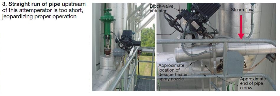
- Proper installation. The desuperheater supplier typically specifies a straight run of pipe upstream of the attemperator equivalent to two to eight pipe diameters; 12-20 diameters downstream. Fig 3 illustrates a desuperheater installation with an insufficient run of straight pipe upstream of the spray nozzle.
- Location of thermocouple downstream of the desuperheater. It should be far enough downstream (at least 25 ft) ensure all water evaporates before reaching the instrument.
- Verify that the steam pipe slopes downward immediately after the desuperheater and that it has a drip leg equipped with a level switch or steam trap to prevent the buildup of water leakage or condensate. Be sure that the blowdown mechanism is working properly.
- Monitor the control valve to ensure valve position has not changed significantly for a given operating condition. If the nozzle assembly were to fail completely, the flow coefficient (Cv) would be much higher than it would were the spray nozzles present. Thus the control valve would operate at a much lower percent-open condition than it would normally.
What to do when the HRSG is out of service and the desuperheater is available for inspection:
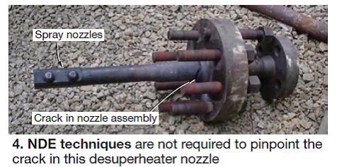
- Remove the desuperheater nozzle assembly from the steam line. Inspect the nozzle assembly for cracking using visual and NDE (non-destructive examination) techniques (Fig 4). A thermal fatigue crack like the one photographed should not be a surprise in plants where the desuperheater cycles excessively. Realize that every time the valve opens, the nozzle assembly goes from about 950F (temperature of steam in the pipe) to 350F (spray water) virtually instantly.
- Inspect the individual spray nozzles to be sure they are not plugged or nicked, or stuck open.
- Look for pitting and/or wear on the inside surface of the first steam pipe elbow downstream of the desuperheater. If you cannot reach the elbow with a borescope, consider an appropriate NDE technique to detect pits or wear.
- Check the desuperheater liner for signs of distortion and/or cracking using a borescope.
Problem avoidance
After you determine the root cause of a desuperheater problem be sure to make appropriate changes to hardware and operating procedures to prevent a recurrence. Regarding operations, several OEMs recommend that the steam temperature at the desuperheater outlet should be at least 50 deg F above the saturation temperature. While appropriate for most designs, at your plant this may mean increasing the unit’s minimum operating load and having less flexibility during transient operations.
Holding values to less than 50 deg F above saturation can be acceptable in certain situations. Variables that impact this decision include desuperheater type, orientation, pipe geometry and straight length upstream and downstream from the attemperator, spray water quality and steam purity, etc.
Recent experience at large combined-cycle plants suggests that you respect desuperheaters for their demanding service conditions and monitor their operation. Inspect just prior to warranty expiration and every 12-18 months thereafter in cycling service and every three to five years in base-load service if they are working properly. Replace every 10 years. CCJ


