By Guillaume GROGNET,
Maintenance Mechanical Manager,
Electricité de France
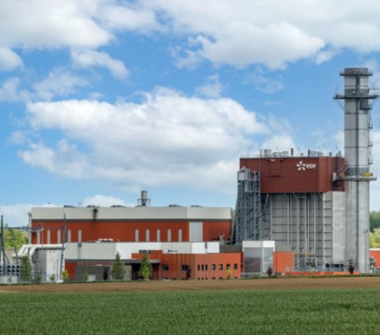
Bouchain CCGT, operated by Electricité de France (EDF), in Northern France was commissioned in July 2016 and has accumulated over 45k operating hours and 650 GT factored starts as of Q4/2023. Due to European grid code and recent grid operation modifications, French and European CCGTs operate in a load-fluctuation-mode, characterized by major and quasi-continuous load swings.
This article details two economizers leaks from 2023.
First leak: March 2023 @ 42 000 FFH
Makeup water assessment monitoring. The first leak occurred in January 2023, detected by HRSG water makeup assessment performed at base load. Some water droplets were observed below the HRSG around affected bundle and even downstream.
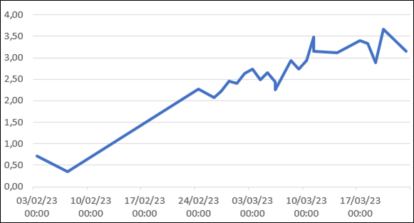
Water makeup assessments are performed at base load. Bouchain’s actual operational profile with operation at partial load and frequent load swings gives us very rare slots to perform precise leak tests. Only a one-hour long accurate leak test is performed per week. Thank to this monitoring, we observed a large leak rate increase during first days of February 2023 as depicted in the chart below which exposes the leak rate evolution from detection to the February 24 forced outage. To be noted that this forced outage is not in relation with this leak. At this time, unexplained makeup water flow was above 3.5 t/h. Taking this unit shutdown opportunity, a borescope gas-side inspection was performed.
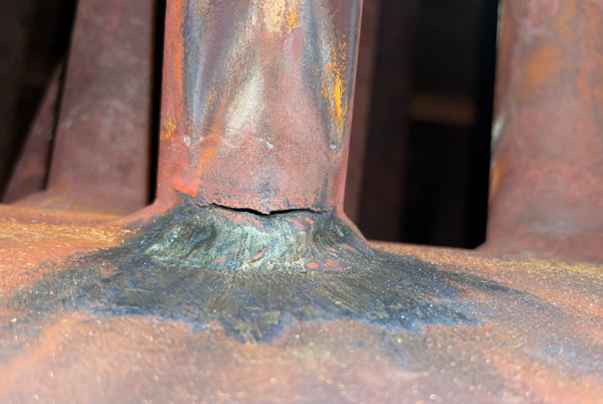
Inspection. Inspection performed with feed water pumps LOTO ON and HP economizer left full of water to easily check number and position of crack(s). One leak is observed on EHP4-1R tube on to lower header welding, on tube side, as shown on pictures below.
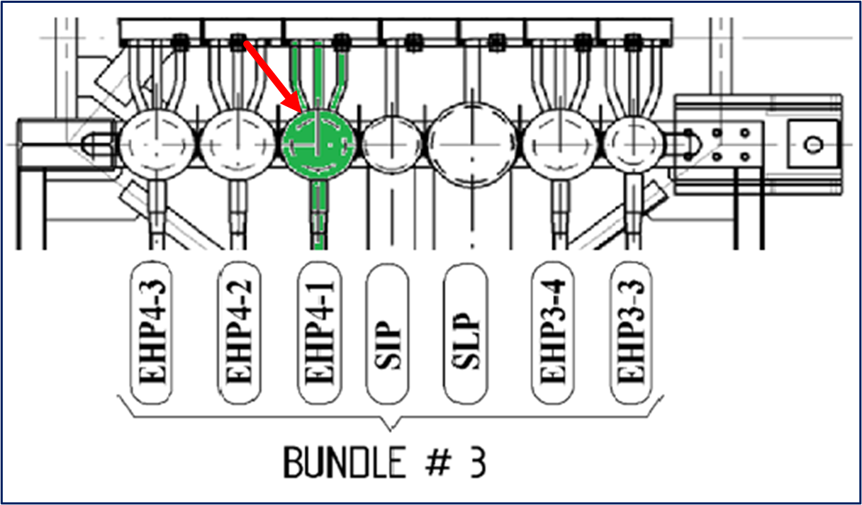
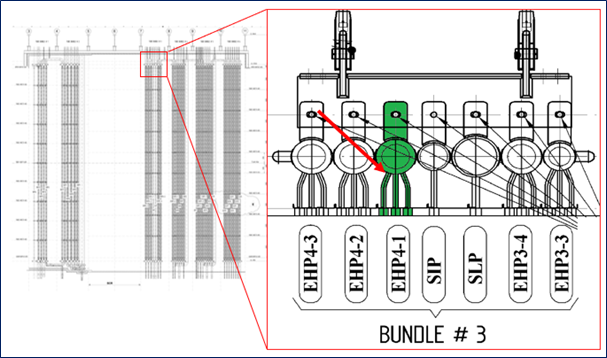
Repair method. HP Economizer exchangers are installed just after a SCR reservation in Bouchain HRSG which gives some access opportunities for repairs. As displayed on beside picture, EHP4-1 is installed in the middle of bundle 3 between IP superheater and EHP 4-2.
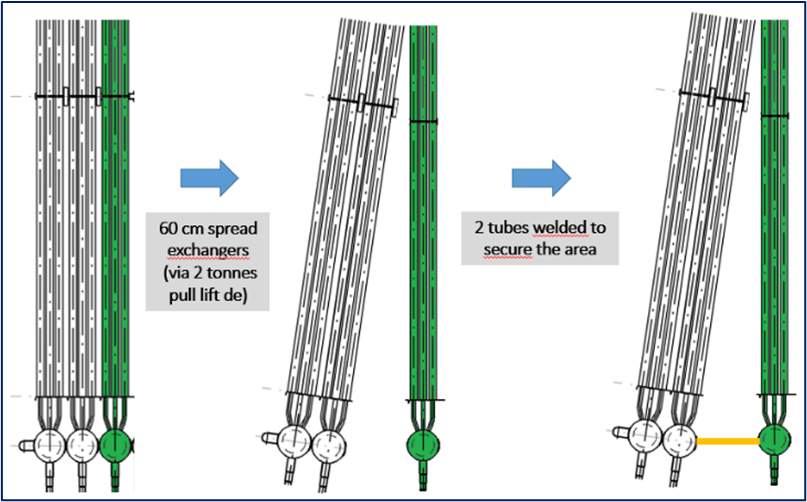
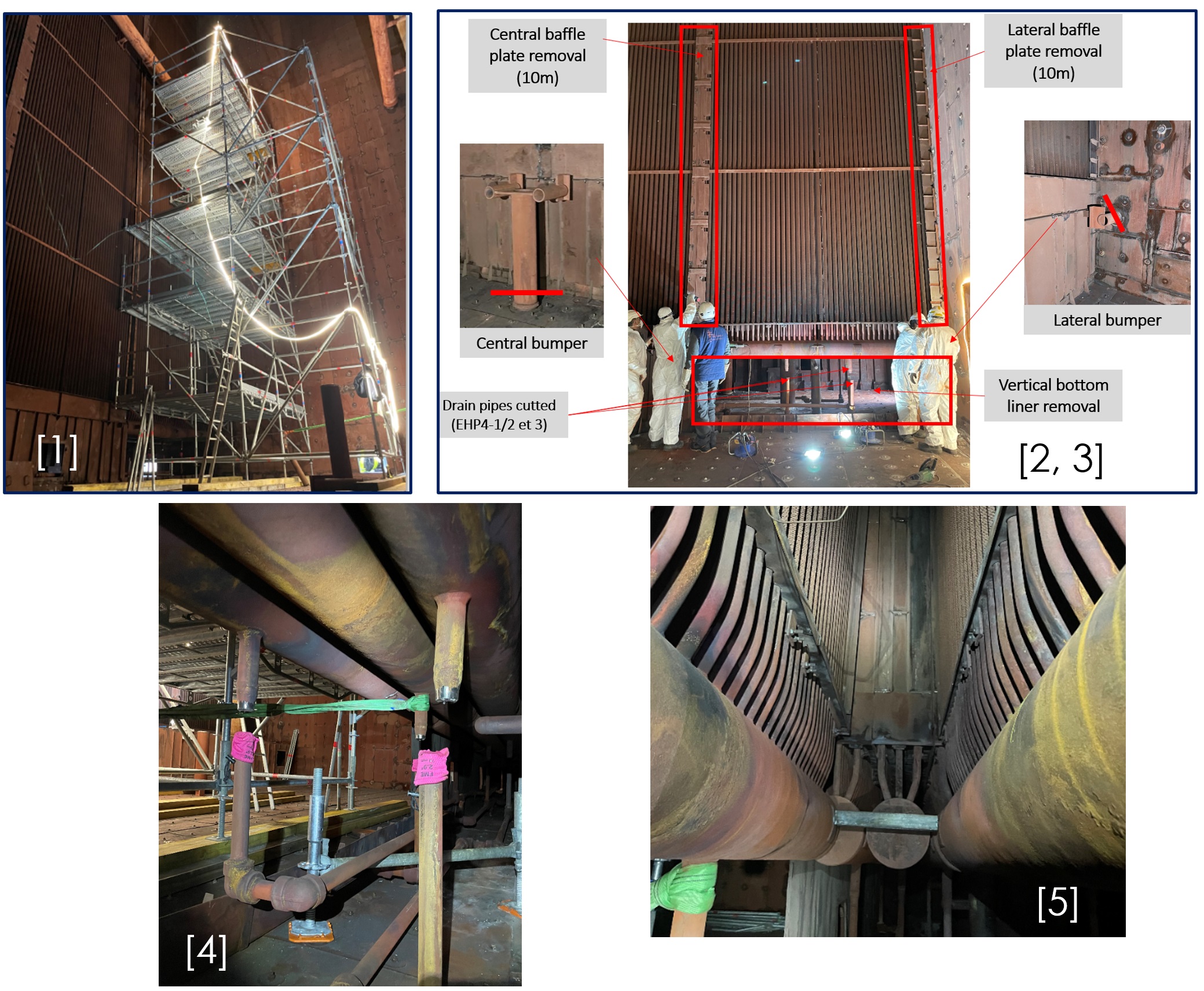
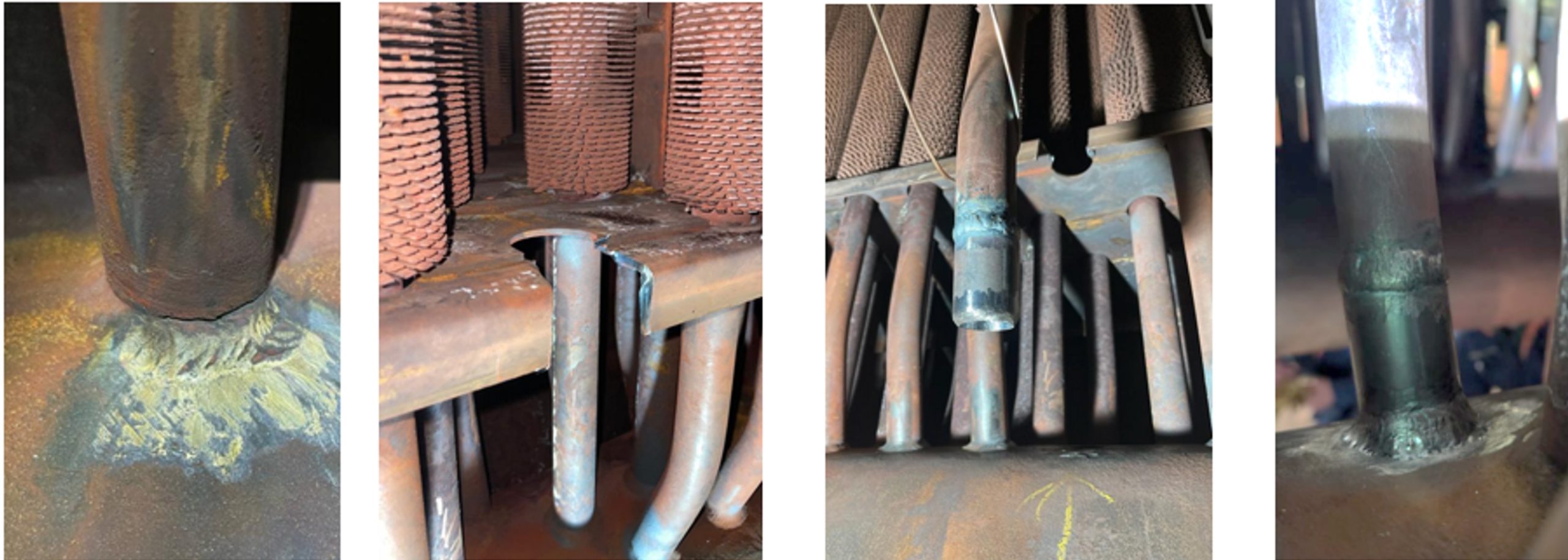
To reach this area, we proceeded with the following sequence and seen in figures below:
- [1] Scaffolding erection in SCR reservation from bottom to half height of the HRSG (approx. 10m),
- [2] Side baffle plate removal till 10 m,
- [3] Bottom bumpers removal,
- [4] EHP4-2 and 4-3 pulling with pull lift hanged on cut drain pipes,
- [5] Securitization of spread exchangers with one welded tube on both exchanger sides.
Crack repair. Once access became available, the crack was visually inspected and then PT performed. The crack is located on the root of the tube-to-header weld on tube side along approximately ½ of the circumference of the tube. Slight erosion of the header is observed which, after measurement represents only 1/10 mm over 42 mm thick header.
Cracked tube area is cut and extracted for RCA purpose. A tube spool is prepared and welded in place of the removed tube. As shown below, tube sheet has been cut to make tube preparation and but welding easier:
Once repaired, the sequence explained previously is redone reverse.
Back on the grid…
Second leak: September 2023 @ 45 000 FFH
Unit is restarted immediately after this forced outage and producing during several weeks without interruption before annual planned outage. Visual inspection is performed on lower and upper headers during this outage, on water side and gas side. Nothing to report. Unit is restarted and on the grid for 2.5 months until a new leak is detected by water drip observation below the HRSG.
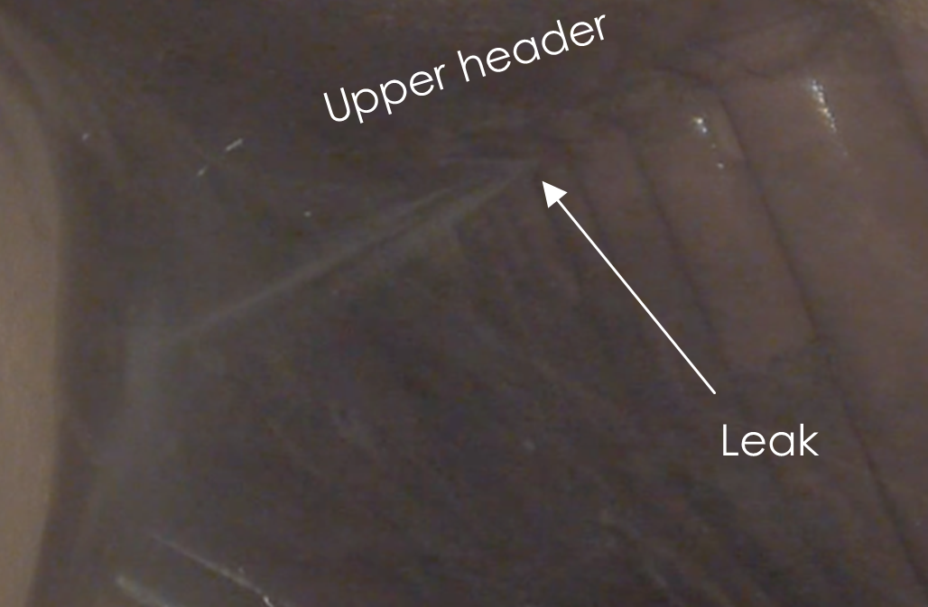
Location. The same method as for the first leak is used for crack localization. This time, the leak is detected on upper tube-to-header weld. BI from gas side picture besides shows the leak which seems to be in the same area as the first one but on the upper tube-to-header weld.
In this case, getting access for repair is much more challenging. Each exchanger is hanged from upper collector and are all in contact providing less than 1 cm of access from the top.
Several methods are available on OEM and field services repairers:
- Classical method consists in cutting first layers of tubes to provide enough access to the welder to be able to repair the leaking tube. In this case, as the leak is located on the 3rd exchanger, this method leads to cut 6 rows of tubes (i.e. approx. 50 tubes). This method has several drawbacks:
-
- It needs approx. 150 welding to restore exchangers and the generation of associated risks in a context of two leaks occurring in the same year and an unknown root cause (RCA still in progress at this time).
- It gives access only to the leaking tube, giving no room for preventive checks or repairs on other tubes of the row.
-
- A second method consists in cutting upper part of the header of the affected tube to give access inside to plug and weld the leaking tube from inside the collector. This method needs also to cut and plug the lower end of the affected tube to prevent from overheating of this “non-cooled tube” during operation. This second method has also several drawbacks:
-
- The affected tube needs to be plugged from both ends which induces to give an access on lower half (like for the previous leak).
- Like for previous solution, no opportunity of proactive checks or repairs on other tubes,
- Very challenging to cut upper header, especially in affected tube area. The location of the tube leads to cut the header in a critical area: very close to inlet connector and hanger.
-
Based on our feedback and on OEM and repair shops experience, no other solution available on the market to avoid hundreds of welding and collector cuttings. In this situation must be designed to try to manage the repair in a different way.
After brainstorming and drawing analysis, a solution appears like an optimal way in terms of planning, technical risks and (very important) inspection/ proactive repairs opportunity for other tubes.
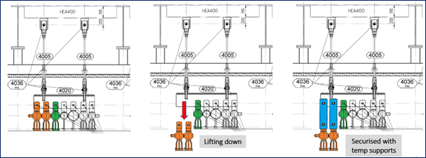
This innovative method consists in giving access to the upper tube-to-header welding area by lifting down the two front exchangers EHP4-2 and EHP4-3 of 25 tons each. The sequence principle is depicted below:
Before lifting, preparation job is needed:
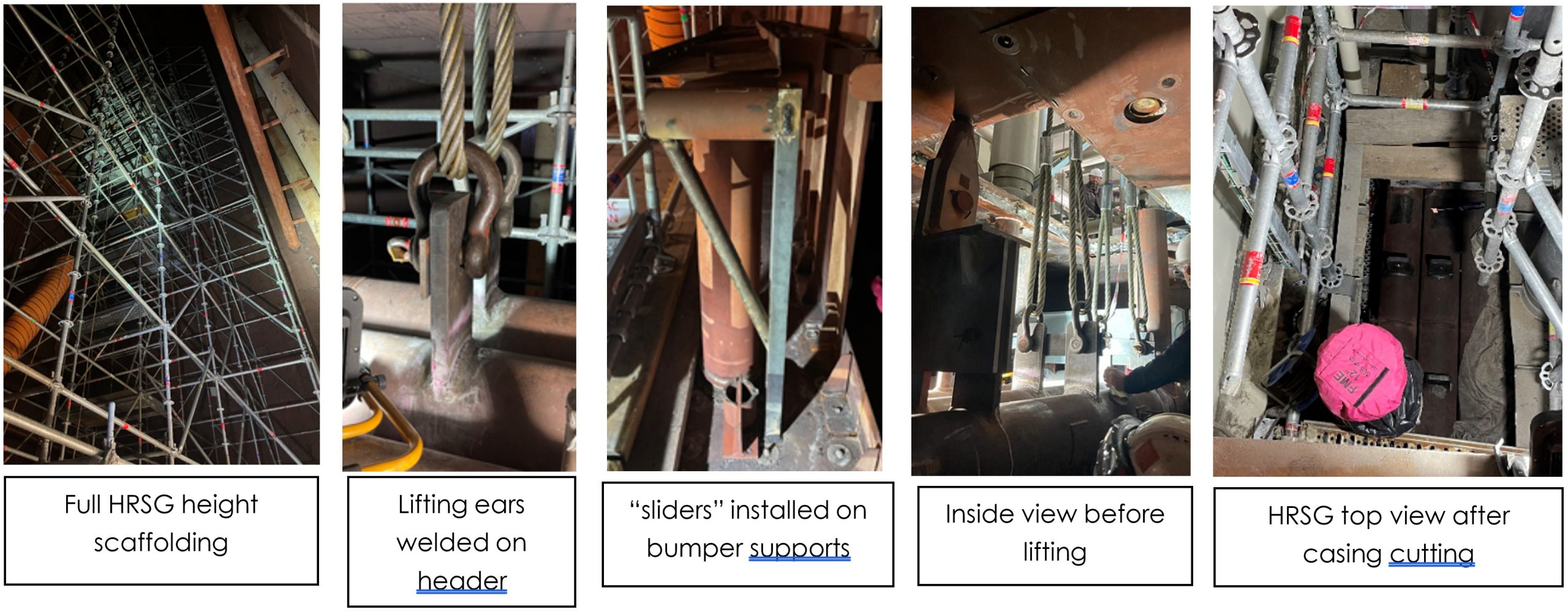
- Erect a full height (20 m) scaffolding in SCR reservation
- Remove side and central baffle plates, bumpers
- Cut jumper between EHP4-1 and EHP4-2
- Cut vent pipe on EHP4-2 to EHP4-3 jumper
- Cut the EHP4-3 to drum pipe
- Weld lifting ears on down lifted exchangers upper headers
- Design and install sliders on cut bumpers supports to guide exchangers during down and up liftings
- Cut HRSG ceiling casing, insulation, and liners to provide a large access for slings and lifting devices perfectly above exchangers.
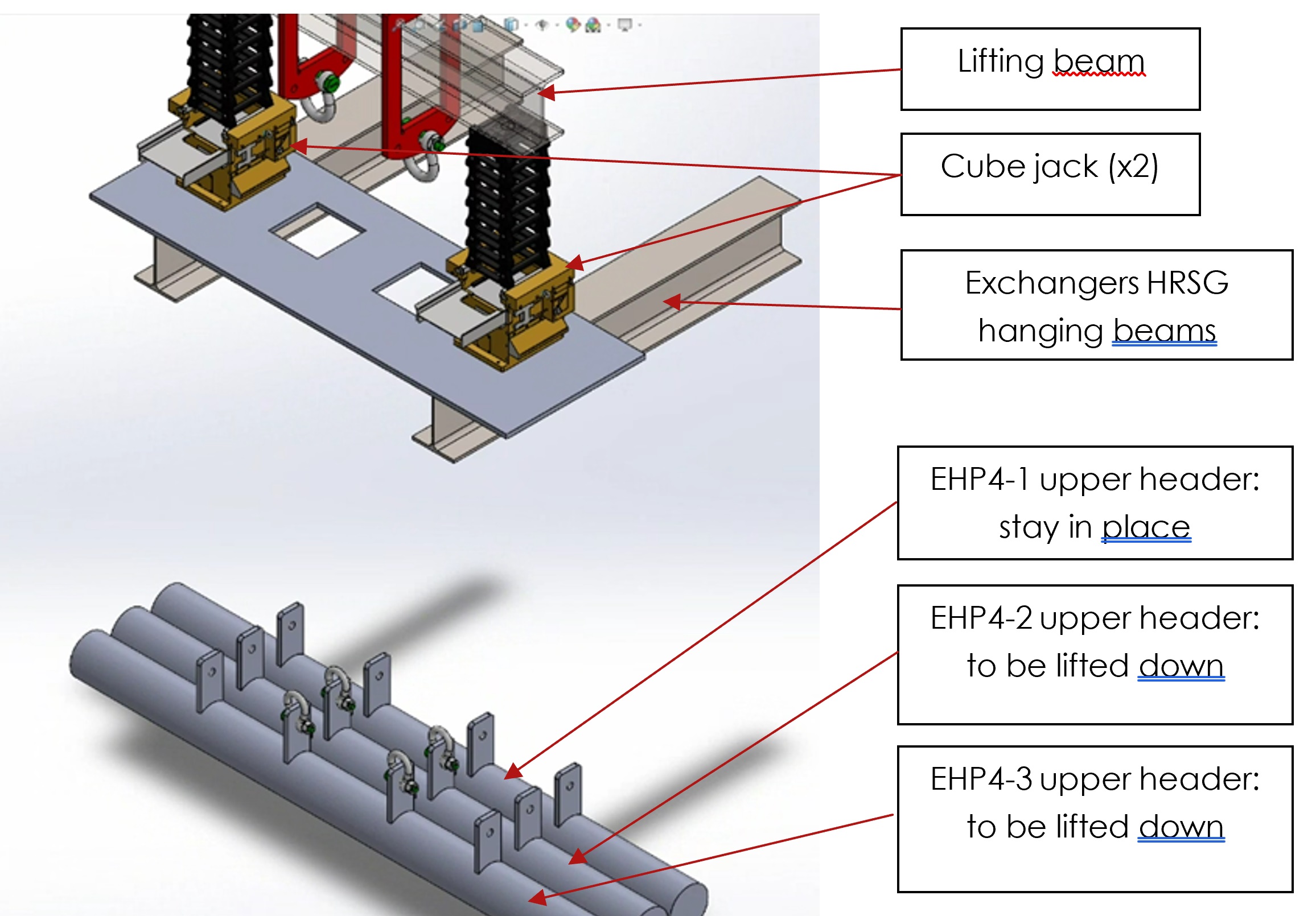
Lifting system. The lifting system has been designed for this specific operation. It is composed by two 50 t “cube jacks” and one beam installed on the top of the casing, seated on the exchanger support beam as shown on the following 3D model:
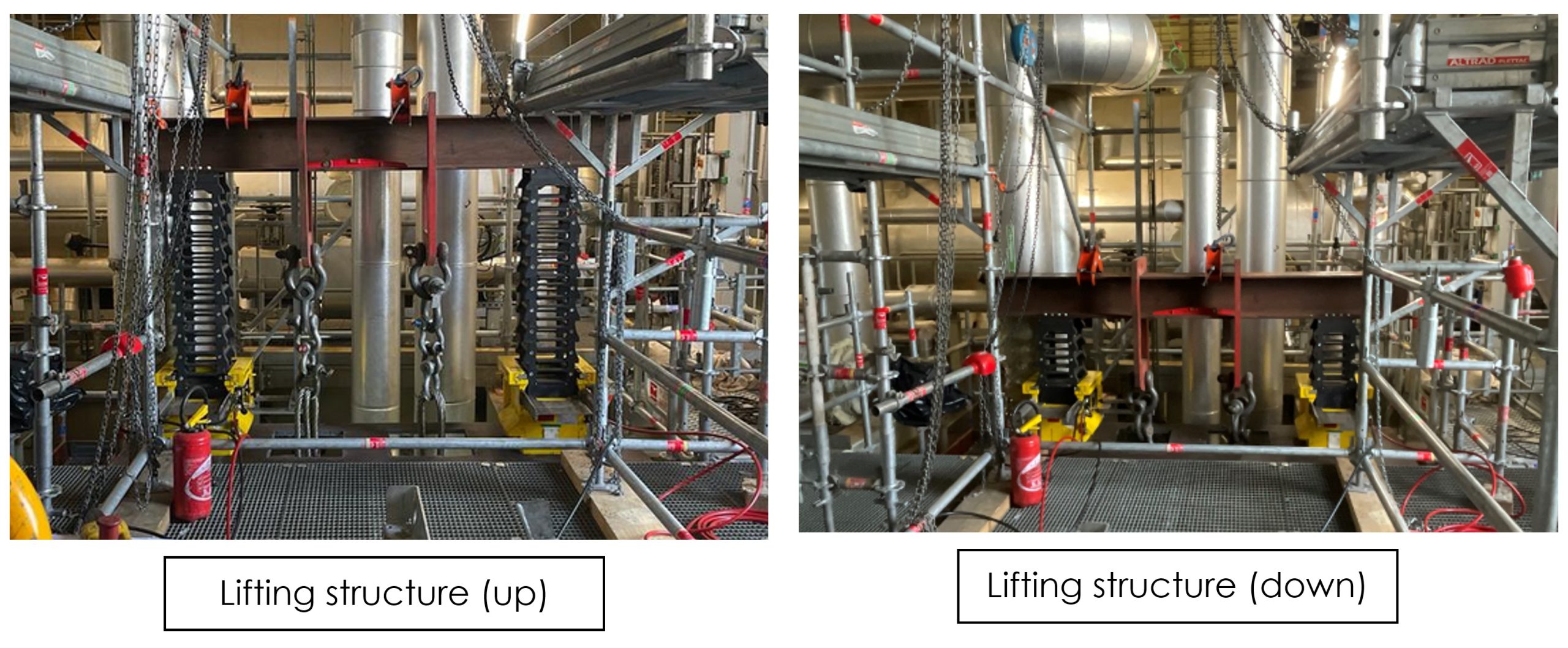
To give sufficient access for the welder, the two exchangers are lifted down around 600 mm and secured with temporary brackets:
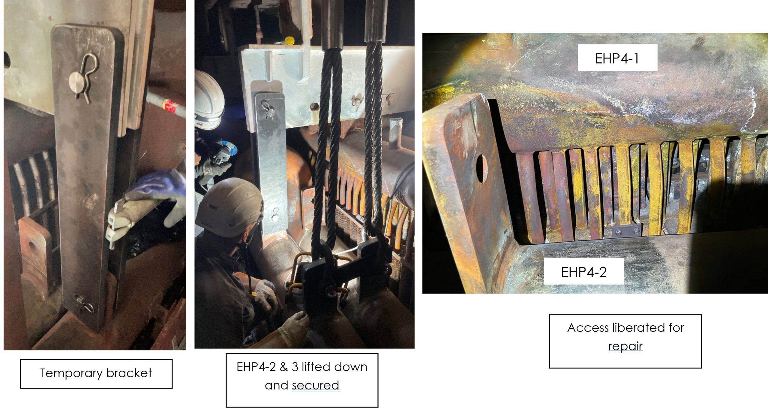
Once access to EHP4-1 liberated, penetrant test is performed on accessible tubes. One linear indication is found on Tube 13 close to the leaking one (Tube 8).
Tube 8 is repaired with the same method as for the first leak, tube 13 is grinded and rewelded.
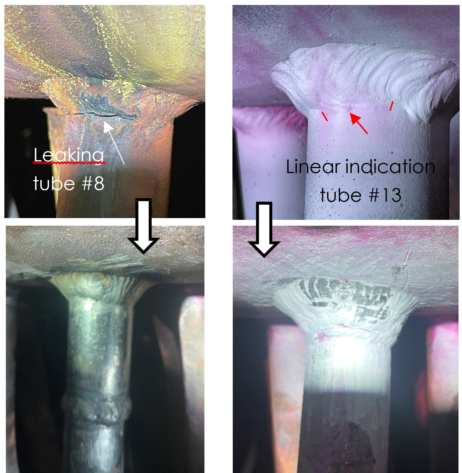
Finding observed on Tube 13 support the decision taken concerning access method. Indeed, the presence of a crack initiated on Tube 13 represents a high risk of leak during winter. Inspection and proactive repair on this time certainly avoided third leak and associated forced outage for repair.
The sequence is then performed in reverse to restore the HRSG for operation.
Root cause analysis
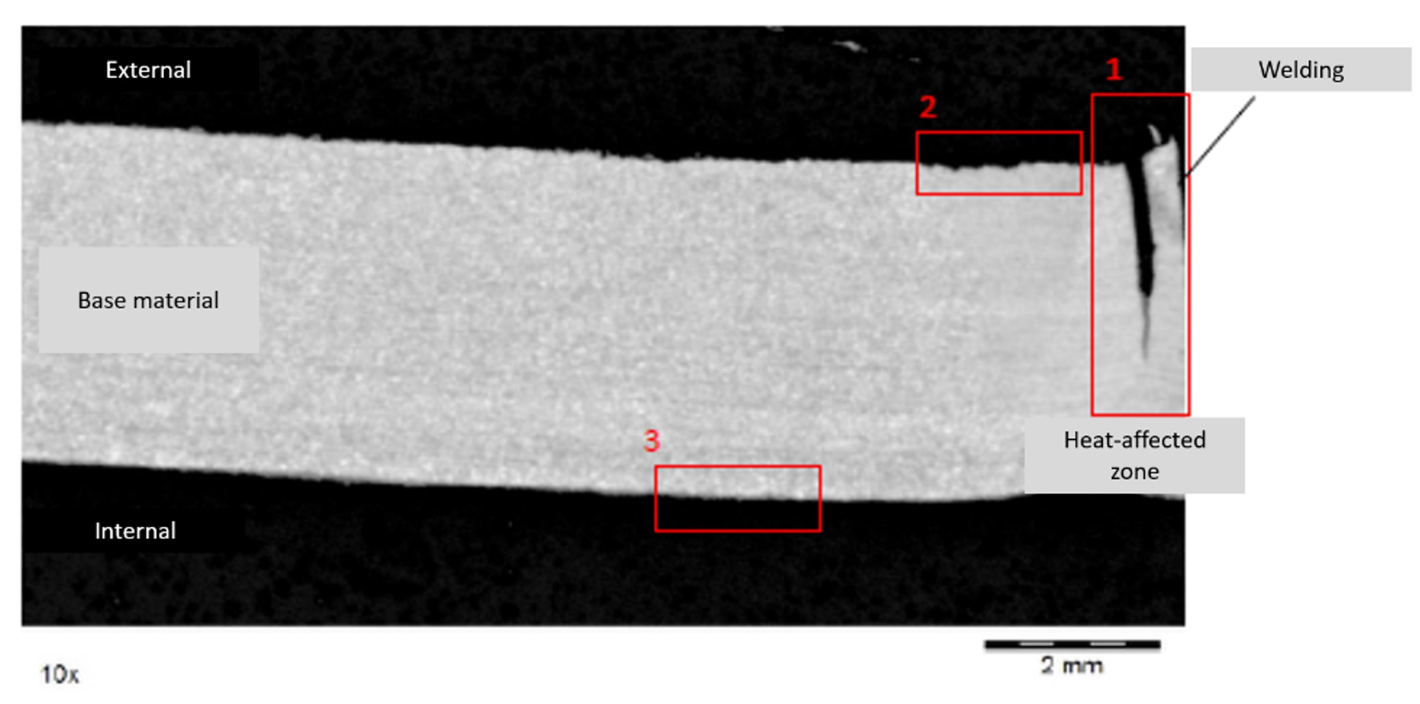
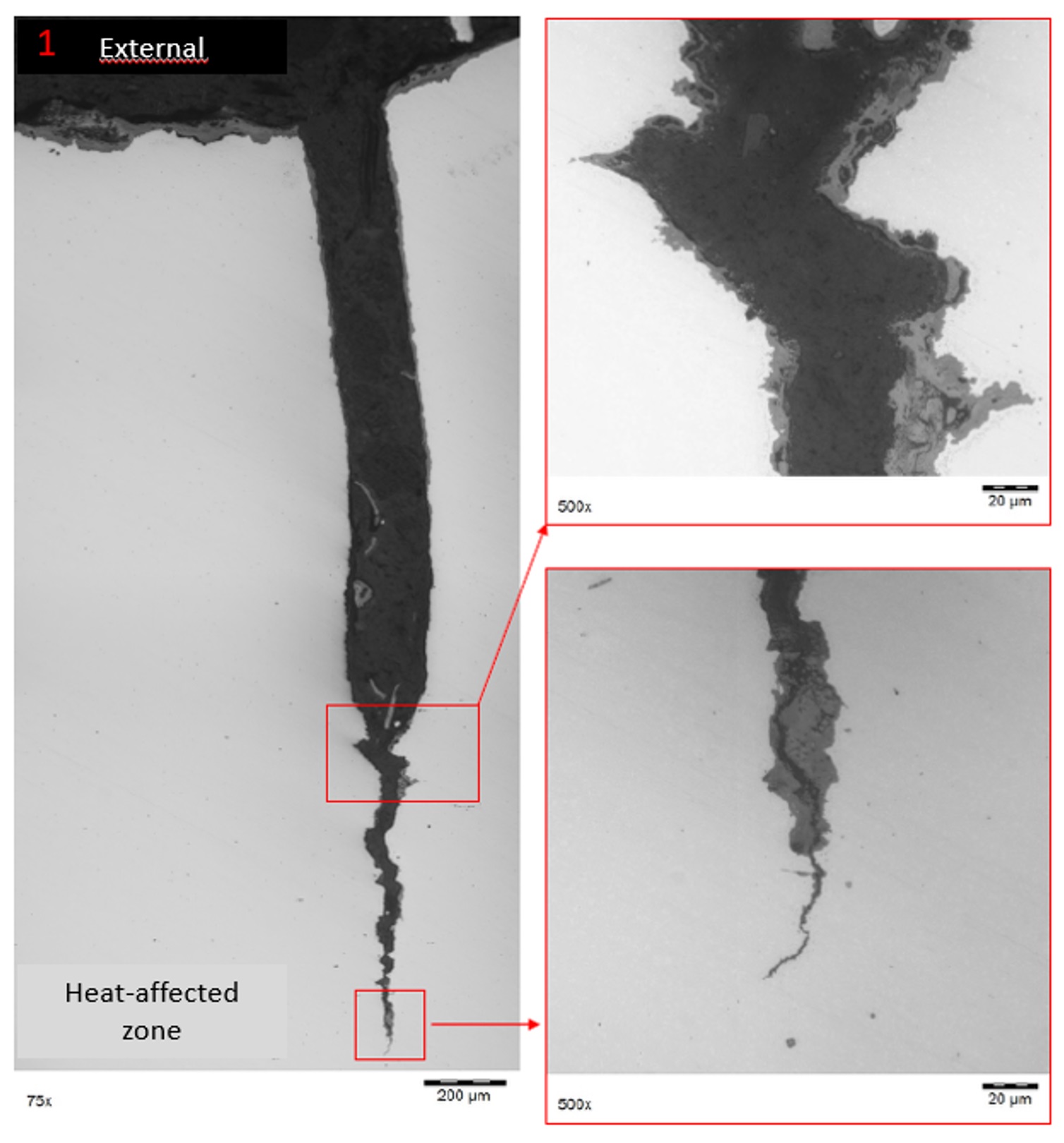
Two cracked tubes have been evaluated and are showing several thin cracks aligned, all in the root of the welding on tube side. “Leaking” cracks, eroded by water during operation with the leak are giving some clues and are already conclusive on thermal fatigue. The analysis of the second tube in a non-leaking area is showing some small cracks not completely opened and so presenting clean thermal fatigue facies.
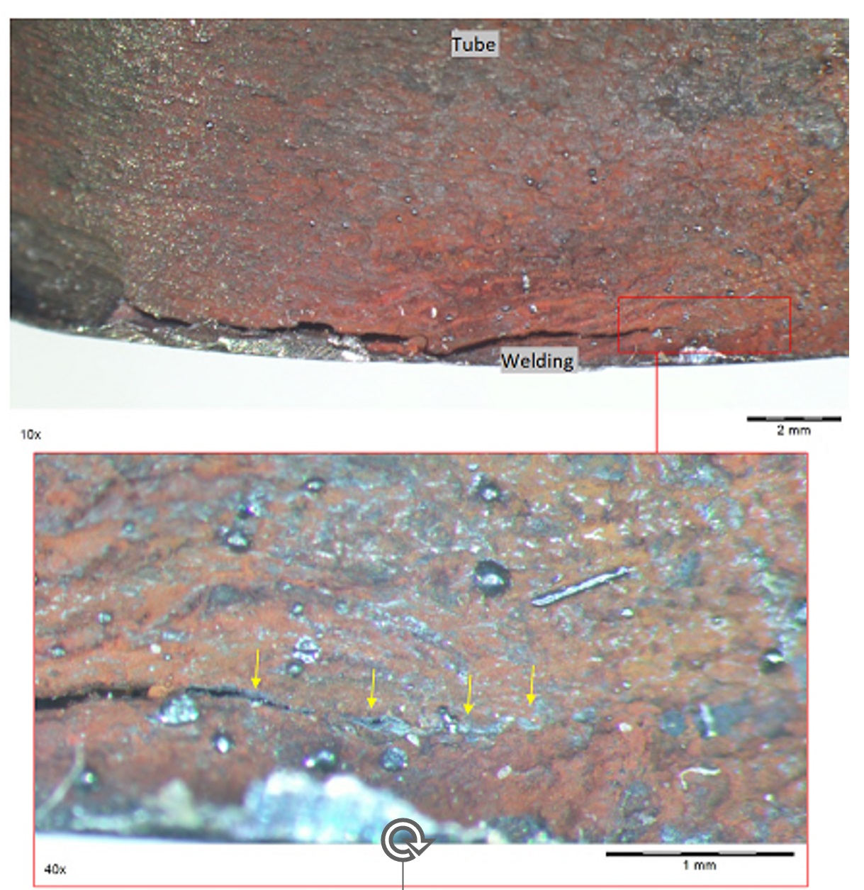
Cracks are initiated on outer diameter of the tube and are evolving quickly through all the thickness of the tube. The connection between this thermal fatigue and the design of economizer/drum approach regulation system must be verified.
Indeed, the approach (difference between HP economizer outlet water temperature and saturation in HP drum) is regulated. To avoid the risk of steaming in HP economizers, a fraction of feedwater flow coming from FWP to HP economizers is by-passing first economizers stages and injected through regulation valve at the inlet of EH4-1. In some CCGT, this “cooling” flow is preheated by very first economizers stages and by-passing only few stages to avoid major ΔT in economizer where the by-pass is reinjected, aiming like 30 to 50°C of ΔT. In Bouchain, as the water is taken directly from HP FWP discharge, the ΔT between FW temp and EHP4-1 inlet is around 100°C. In addition to this poor by-pass design, 2°C minimum approach is maintained by an on/off regulation which leads to very fast and wide opening of the regulation valve. Those two points, combined with a very high load fluctuation rate led to a huge fatigue duty applied on EHP4-1.
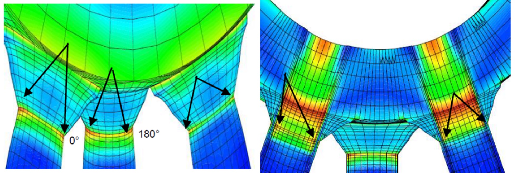
In this context, and to quantify magnitude and consequences of this load on the harp, the RCA has been completed by a finite element analysis, performed by EDF internal experts. Following figures are representing the result of the calculation during the most stressing operation case: the opening of the inching valve inducing approx.100°C delta T on the exchanger.
The highest stress is precisely located in the root of the welding on tube side. The stress is a bit higher on outer diameter (vs inner diameter) of the tube but the magnitude is comparable on both sides. Inlet water connector area is the highly loaded part of the exchanger and stress level is highly impacted by the geometry of the welding. This impact is difficult to predict with the FEA but with a theoretical 45° geometry of the fillet root, the stress is reaching around 320 MPa with a maximal admissible stress of 125MPa for this SA210Gr.C. To be noted that the geometry of the welding is not specified by the manufacturer.
Once this maximum stress calculated, expected lifetime has been determined thanks to EN13445. Considering operating temperature, calculated stress, material and welding configuration, the expected fatigue lifetime of this tube to upper header welding is estimated around 6000 cycles. A long-term analysis on historical data available in Bouchain PI historian system is showing 5764 inching valve large openings. Even if the standard calculation is taking some hypothesis and the leaking probability at this number of cycles is very low but the magnitude is very close to the fatigue load taken by leaking tubes. In this context, a long-term solution must be designed and implemented to avoid more leaks and associated forced outages.
Fatigue reduction
To avoid potential fatigue, a preventive margin on the approach has been added to avoid wide opening of the valve. In a second step, new regulation has been tested to avoid major temperature fluctuation and to reduce ΔT amplitudes. This modification reduces the stress applied on the exchanger and delays the risk of new leak by several months or years, depending on efficiency of ΔT reduction but will not be sufficient for the long term. The exchanger must be reinforced, totally or partially replaced, or upgraded. Solutions are currently being evaluated with the hope of having the opportunity to complete repairs during ongoing steam and gas turbine major inspections. Any feedback from vendors or users on this type of situation and solution implementation will be highly appreciated. Thanks and stay tuned for more results!