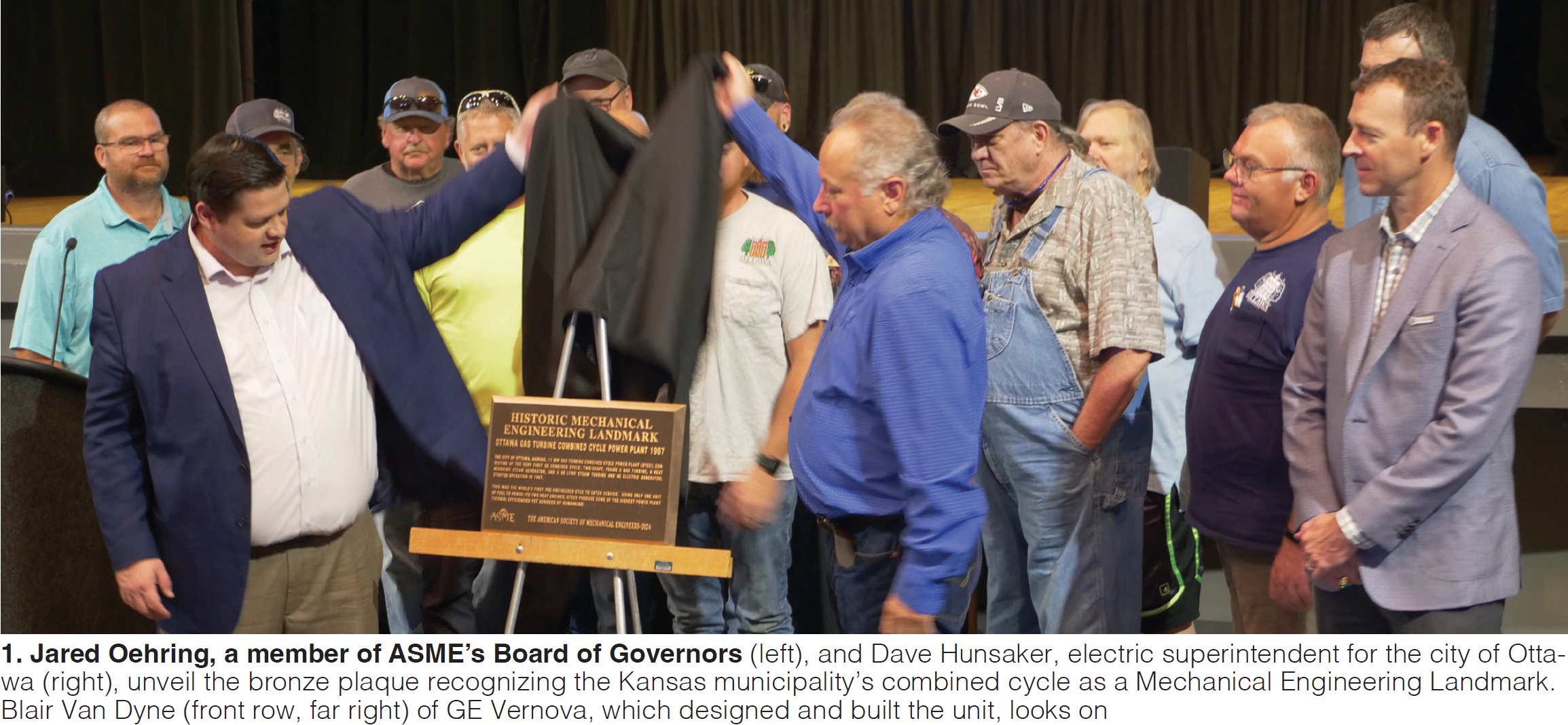
The city of Ottawa’s gas-turbine-powered combined cycle was honored as an Historic Mechanical Engineering Landmark by the American Society of Mechanical Engineers, Sept 13, 2024, in a special ceremony conducted in the Ottawa Memorial Auditorium. Dave Hunsaker, electric superintendent for the city, accepted the award from ASME Fellow Jared Oehring, a member of the society’s Board of Governors (Fig 1).
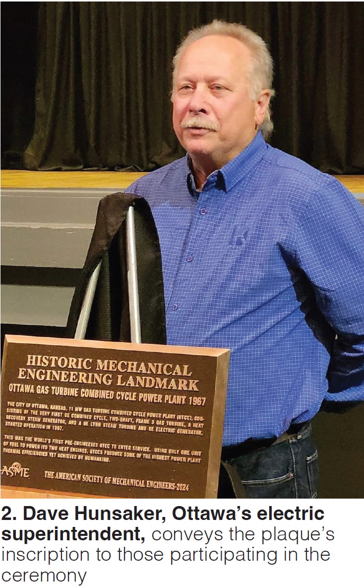
The unit is the oldest extant unit of its type and representative of a major breakthrough in heat-engine design. The inscription on the bronze plaque (Fig 2), prepared by ASME’s History and Heritage Committee, reads as follows:
The city of Ottawa, Kansas, 11 MW gas turbine combined cycle power plant (GTCC), consisting of the very first GE combined cycle, two-shaft, Frame 3 gas turbine, a heat recovery steam generator, and a GE Lynn steam turbine and GE electric generator, started operation in 1967.
This was the world’s first pre-engineered GTCC to enter service. Using only one unit of fuel to power its two heat engines, GTCCs produce some of the highest power plant thermal efficiencies yet achieved by humankind.
Recognition as an ASME Historic Mechanical Engineering Landmark is a significant accomplishment (sidebar). Ottawa’s combined cycle is the 283rd project so honored since the program’s inception more than 50 years ago and only the second Landmark in the state of Kansas. The first, Landmark No. 127 (1987), is the Big Brutus mine shovel. Its 90-cubic-yard bucket removed 135 tons of overburden with each scoop in the surface mining of coal from 1963 to 1974.
Gas-turbine history
The transition from fossil-fuel-fired electric generation based on the Rankine cycle to the Brayton cycle began in 1939 with commercial operation of the municipal power station in Neuchâtel, Switzerland.
This was the world’s first successful use of a gas turbine to drive an electric generator. The 4-MW simple-cycle plant had an efficiency of 17.4%. It was designated by ASME as Mechanical Engineering Landmark No. 135 in 1988 (sidebar).
Gas-turbine developments came quickly after World War II, motivated by the booming military and commercial aviation industries. At General Electric, a group of engineers who had participated in the design and development of aircraft jet engines began work on a gas turbine suitable for industrial and utility service.
While many of the metallurgical advancements and technologies developed by the aviation industry could be applied to land-based gas turbines, ruggedness and long life, rather than light weight, were the important design considerations for power generation. The blending of jet-engine and steam-turbine designs resulted in what came to be referred to as heavy-duty gas turbines for on-ground applications.
Landmarks highlight significant historic mechanical engineering achievements
ASME encourages public understanding of mechanical engineering and fosters the preservation of its heritage. The society formed a History and Heritage Committee of mechanical engineers and technology historians in 1971 to examine, record, and acknowledge achievements of particular significance.
ASME’s technology library at www.asme.org/about-asme/engineering-history/landmarks offers a fascinating trip through the history of mechanical innovations that have influenced the development of civilization and industry, as well as public welfare, safety, and comfort.
Mechanical Engineering Landmarks are existing artifacts or systems representing significant technological accomplishments. Often, they are the last surviving examples of an important device, or machines with some unusual distinction.
H&H committee members participating in the evaluation of the Ottawa combined cycle for Landmark status included the following:
- Lee S. Langston.
- Thomas H Fehring, PE.
- Marco Ceccarelli.
- Martin C Ross, PE.
- Robert T Simmons, PE.
- Terry S Reynolds.
- Herman Viegas.
Perhaps the earliest use of these ruggedized engines for electric generation was in GT-electric locomotives. First demonstrated in 1948, Union Pacific went on to purchase several dozen locomotives from ALCO (American Locomotive Co) with GE providing on-base gas-turbine power to the motors for long rail deliveries in the West.
These machines soon fell out of favor with the public, according to some industry experts, because of the high-frequency noise generated by the gas turbines’ axial-flow compressors. An inlet-silencing solution was not introduced until late in the 1950s when gas turbines for rail application already were being forced into retirement.
By contrast, electric power producers welcomed gas turbines, as did companies involved in gas/oil transmission where they were valued as drivers of pumps and compressors. The first GT installed by a US electric utility was applied in a combined cycle at Oklahoma Gas and Electric Co’s Belle Isle Station in 1949.
But this was not one of today’s combined cycles. Energy in the exhaust gas from the 3.5-MW gas turbine (a GE MS3001, a/k/a Frame 3) was used to heat feedwater for a 35-MW conventional steam unit. OGE doubled down on its innovation in 1952, repowering another Bell Isle unit in the same manner.
Most early combined-cycle systems were adaptations of conventional steam plants with the GT exhaust serving as combustion air for their fully fired boilers. The efficiency of this type of combined cycle was about 5% to 6% higher than that of a similar conventional steam plant. These systems could use bare boiler tubes economically because of the high mean temperature difference between the combustion products and the water/steam.
Equipment to economically weld continuous spiral fins to tubes was introduced to boiler manufacturers in 1958, enabling the next step in combined-cycle design. So-called heat-recovery combined cycles, capable of capturing the sensible heat in GT exhaust gas, were made possible by welded finned tubes.
For engineers knowledgeable in thermodynamics, this was big: Fueling a gas turbine with natural gas and using its exhaust gases to make steam to drive a steam turbine provides two prime movers to generate electricity using only one unit of fuel. This combined-cycle arrangement currently has yielded the highest thermal efficiency of any heat engine that has ever been produced, and is the one preferred today by electric power producers.
Today’s three leading suppliers of large combined-cycle powerplants—GE Vernova, Siemens-Energy, and Mitsubishi Power—all offer units with thermal efficiencies in the 60% to 65% range.
GE introduced the pre-engineered combined cycle to the electric power industry in 1967 under the tradename STAG (STeam And Gas). Less than four years later it had four competitors: Westinghouse Electric Corp, Turbo Power and Marine Systems Inc (a subsidiary of Pratt & Whitney), Turbodyne Corp (affiliated with Brown Boveri-Sulzer Turbomachinery Ltd and Worthington Turbine International Inc), and Stone & Webster Engineering Corp.
But GE had the only success story among the firms offering pre-engineered combined cycles. Its first two systems were rated 11 and 21 MW, both incorporating one gas turbine (Frame 3 for the smaller unit, Frame 5 for the larger), one heat-recovery steam generator (HRSG), and one steam turbine/generator.
The city of Ottawa (Kansas) commissioned the first STAG unit (11 MW) in 1967 (a Model 103) and opened the proverbial flood gates for pre-engineered systems, with unit sizes growing exponentially in short order.
Example: Jersey Central Power & Light ordered the first multi-shaft STAG unit (four gas turbines, one steam turbine), rated 340 MW in 1971. By the end of 1974 15 more STAG systems (single- or multi-shaft configuration) were ordered by eight utilities. The largest had eight gas and two steam turbines with the capability to produce nearly 600 MW.
The bottom line: In less than a decade, the industry-wide combined-cycle “movement” launched by a small midwestern municipal utility was installing power-generation systems 50-fold larger.
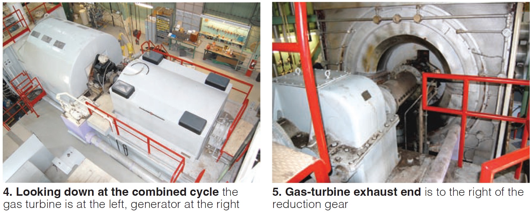
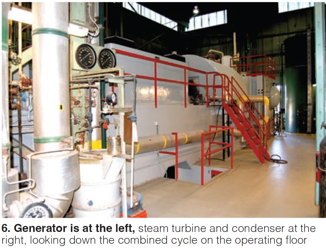
Commercial success. Ottawa demonstrated the efficacy of a pre-engineered combined cycle of relatively simple design for producing electric power reliably and at low cost in baseload service. Its power train, consisting of a starting motor, MS3002 gas turbine, reduction gear, axial-flow steam turbine, and generator powered by both the gas and steam turbines, is base-mounted, with components arranged in tandem on a single shaft (Figs 3-6).
The unit generated 11.5 MW at the unusually low net plant heat rate (for that time) of 11,280 Btu/kWh, yielding an outstanding thermal efficiency of 30.25%. The careful integration of proven components, a STAG feature, contributed to the plant’s low installed cost—quoted at $1.745 million.
Important to note is that Ottawa’s guaranteed heat rate, based on the higher heating value of natural gas, 1000-ft elevation, and 80F ambient, was a 12% to 18% improvement over comparable steam plants. Recognize that Ottawa was designed prior to acceptance of ISO standards which calculate GT performance based on a sea-level location, 59F ambient, and 60% relative humidity.
Ottawa’s STAG Model 103 has a two-bearing, statically excited, air-cooled generator with the gas turbine coupled to the forward end and the multi-stage steam turbine to the aft end. The latter, which has 14-in. last-stage blades, has no throttle control valves. They are unnecessary as steam pressure varies over the load range in direct relation to the GT exhaust temperature.
This results in a constant volume flow of steam entering the unit during normal operation. The steam inlet is equipped with a stop valve and motor-operated trip throttle valve for control during starting, and complete protection in the case of a full-load or overspeed trip.
The steam turbine exhausts axially to a floor-mounted condenser. A single-cell induced-draft cooling tower and full-size circulating-water pump supply the total cooling-water flow requirement of the condenser, gas turbine, generator, and all Rankine cycle accessories.
An extended-surface heat-recovery steam generator (HRSG) recovers thermal energy from the nominal 970F gas-turbine exhaust gas to produce 46,500 lb/hr of 400-psig/820F steam—assuming the unfired HRSG receives the design-basis exhaust-gas flow of 382,500 lb/hr and feedwater at 110F. Demineralized makeup water is supplied to the HRSG. Note that the HRSG, as well as the gas and steam turbines, were made by GE.
Ottawa’s modular HRSG, no longer a GE product, offered the benefits of reduced installation time and cost. The boiler was non-radiant, so refractory and waterwalls were not required. Forced circulation and small-diameter finned tubes contributed to a compact, shippable boiler for exhaust-gas flows up to about 1.5-million lb/hr—or about four times that required by Ottawa.
Plus, unrestrained headers of intermediate thickness and all-welded construction eliminated direct tube-to-steam-drum joints while minimizing the effects of thermal shock.
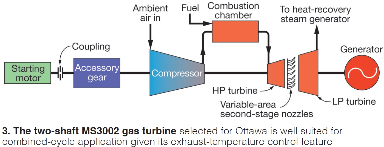
The MS3002F consists of a so-called HP turbine set—it incorporates a 14-stage axial-flow compressor, combustion section, and HP turbine—and the LP turbine, which is connected to the generator. HP turbine inlet temperature is 1600F when the unit is at baseload. Exhaust gas exiting the HP section flows through variable-area, second-stage nozzles before entering the LP turbine (refer back to Fig 3).
The two-shaft gas turbine, most commonly applied in gas-compression and pumping service, is particularly well-suited to a combined-cycle application because of its exhaust-temperature control feature. By varying the angle of the second-stage nozzles, it is possible to maintain nearly constant exhaust temperature (and steam conditions) over much of the load range. Part-load performance is improved considerably by holding the steam conditions constant.
The HP turbine set has three bearings and turns 6900 rpm; the two-bearing LP turbine, which operates at a nominal 6000 rpm at rated load, is connected to the 3600-rpm generator through the reduction gear shown in Fig 5. The generator is rated 13.5 MVA, 12.5 kV, 0.85 pf.
Once synched to the grid, the LP turbine shaft has to run at precisely 5979 rpm for the generator to produce 60-Hz power. When load is increased or decreased, HP turbine speed and the variable-area, second-stage nozzles respond to maintain LP turbine speed.
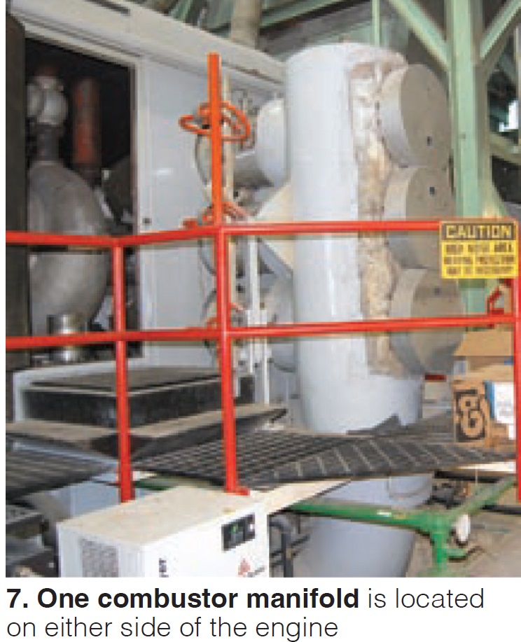
Combustion system for the MS3002F is unique. There are three combustors on each side of the engine. Two of the three chambers on each side have spark plugs; the third has a flame detector (Fig 7).
The STAG 103 came equipped with dual-fuel capability. When the combined cycle was installed, the city generated all of its power, which it did until 1979, with the GE unit in baseload service. Once Ottawa began purchasing power from the grid, the STAG 103 was relegated to peaking service and the faster-starting recip engines (two rated 6 MW, one 3.6 MW and one 3 MW) better suited for this type of service were dispatched ahead of it. The engines can be at full power in five minutes; it takes the STAG 103 about 45 minutes for a cold start.
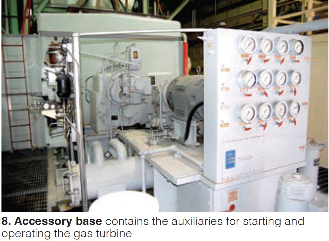
The accessory base contains the necessary auxiliaries to start and operate the unit (Fig 8). An ac starting motor is coupled through an accessory gearbox to the HP turbine shaft at the compressor end. Motor-driven lube-oil pumps, lube-oil cooler, and oil filter are located above the oil reservoir.
The original control system had at its heart a mechanical/hydraulic control device known as a Fuel Regulator, manufactured by Young & Franklin. It controlled fuel flow, and the power output of the LP turbine. HP turbine speed was controlled by another Y&F device: a nozzle regulator. In 1992, Ottawa upgraded to a Woodward NetCon control and protection system to improve starting reliability. Conversion of the gas turbine from dual fuel to gas-only was accomplished at this time as well.
Operation. Startup of the STAG 103 is semi-automatic. More specifically, many of the functions and operating sequences are manual with several sub-loop operations automatically sequenced and performed. Startup permissives include having turning gear “off” and key equipment in operation.
The unit then is cranked for starting by a 250-hp electric motor. When it reaches about 25% of rated speed, retractable spark plugs ignite the fuel/air mixture in four of the six combustion chambers. Crossfire tubes ignite the combustible mixture in the unfired chamber in each bank.
Ignition is maintained for a short period. When combustion becomes self-sustaining, the unit automatically comes to the so-called warm-up condition with the HP turbine set held at reduced speed and firing temperature until steam is produced and all required pre-acceleration conditions are in effect. At that point, gas-turbine acceleration is initiated manually and the STAG 103 comes up to governing speed. The generator is synchronized manually.
Maintenance history. The most recent borescope inspection, conducted by Dave Lucier of PAL Turbine Services about a dozen years ago, found no surprises and concluded that the gas turbine was fit for duty.
The last hot-gas-path inspection had been conducted early in 2001. At that time, maintenance personnel found the engine dirty but in good condition, especially considering the number of hours since the previous overhaul. Some erosion of compressor blades was noted and the HP- turbine bucket tips had rubbed on the lower shroud blocks. Plus, all buckets were frozen in the dovetail fits. The rotor was overhauled in a Houston shop.
Work also was required in the combustion section. Small cracks in liners and transition pieces required repairs, and there was other heat-related damage as well. Bearing wear was in evidence, too. The load-carrying surfaces of journal bearings 1, 2, and 3 were repoured after inspection. Contractor personnel believed that bearing issues contributed to accessory-coupling misalignment and wear and it was targeted for replacement or repair.
End notes. The Ottawa combined cycle was the first of only two STAG 103s made by GE. The second was installed by the City of Hutchinson (Minn) in 1971. Industry demand at that time was for larger power generation systems. In fact, after 1972, no pre-engineered combined cycles smaller than 100 MW were ordered by US utilities. Economy of scale ruled.
Ottawa logged only about 11,000 operating hours after hitting its 100,000-hr milestone at the end of 1993. This industry icon was retired in place in 2020, after spending two decades in standby service. It was started periodically for training and equipment-preservation purposes.
Hutchinson’s STAG 103 was taken out of service in 2019 and has been dismantled.
Today the city of Ottawa (2020 population, 12,625) purchases most of its power for its 6400 meters from the Grand River Dam Authority, Western Area Power Administration, Southwestern Power Administration, Kansas Municipal Energy Agency (Marshall Wind Farm), and the Buckeye Wind Energy Center. The municipal’s four engines remain in standby service.
The city also owns a 5.2-MW share of Dogwood Energy Center, Pleasant Hill, Mo. It is an efficient 650-MW, natural-gas-fired F-class combined cycle.
Ottawa receives 161-kV power at two of its three interconnections and 35-kV power at the third, which is located at the generating plant. Distribution throughout the city is via about 12.4- and 4.6-kV lines.
Acknowledgements
Compiling the history of the Ottawa combined cycle involved the work of many people, especially the following:
- City of Ottawa. Dave Hunsaker, Leon Wildeman (ret).
- ASME H&H Committee (inactive). Lee Langston, Tom Fehring, Steve Walton, Virginia Ross.
- GE. Bob Johnston (ret), Dave Lucier (ret), Tom Freeman.


