GENERATOR USERS GROUP
GUG: User presentations
GUG: Vendor presentations
GUG: Consultant presentations
“Detecting and Identifying Generator System Conditions with Radiated EMI Measurements,” James E Timperley, Charles Taylor Technical Services.
Jim Timperley is highly respected for his knowledge on the use of radiated electromagnetic- interference (EMI) measurements for identifying abnormal conditions in generators and associated electrical equipment. Partial discharge and arcing are among the more than 60 conditions radiating radio-frequency energy that can be identified with the handheld EMI detector known as the “sniffer,” shown in Fig 8. It is designed to measure frequencies from 35 kHz to 390 MHz.
The sniffer, Timperley told attendees, provides information on the physical location of developing deterioration and helps pinpoint where maintenance activity is required to prevent failures and lost production. He offers case studies of generator, bearing, exciter, bus, transformer, and turbine problems in his presentation—ideal for a lunch-and-learn in the plant break room.
To dig deeper on the subject, read “Simple EMI Test Detects Failing Joints, Promotes High Plant Availability,” by Consultants Clyde V Maughan and James E Timperley, in CCJ No. 60 (2019), p 20. You can access it by using the search function on the CCJ home page at www.ccj- online.com
“Magnetic Field Measurements in Powerplants and How This May Limit Workers with Pacemakers,” James E Timperley, Charles Taylor Technical Services.
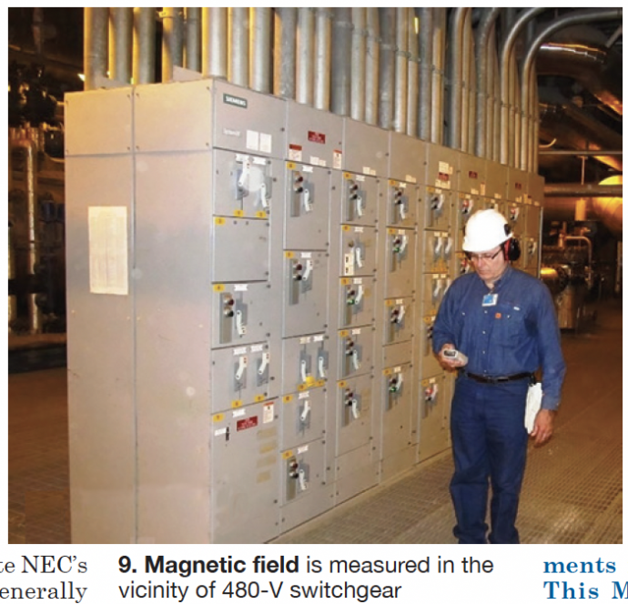
By some counts, Jim Timperley says, more than 300,000 electronic medical devices—such as pacemakers, defibrillators, cochlear, and neurostimulators—are implanted in Americans annually. This means that perhaps 1% of all people entering a powerplant may have some kind of electronic medical device. Providing a safe working environment for these individuals is very important (Fig 9).

Electrical interference can pose a serious problem: It can disable any of these electronic devices. This danger can be from high-voltage electric fields, as in a switchyard, or high magnetic fields near large generators, bus systems, and/or transformers. Plant personnel normally are protected against dangerously high voltages by secure fences or metal structure.
However, high magnetic fields are another matter. Signage warning to maintain a safe distance is a necessity. Timperley offers guidance on where to place signs or limit personnel exposure.
The editors suggest that you access it on the Power Users website at www.powerusers.org. Alternatively, read “Working Safely in a Powerplant with a Medical Implant,” by James E
Timperley, in CCJ No. 64 (2020), p 110. Access by using the search function on the CCJ home page at www.ccj-online.com
“Combined-Cycle Plants: Most Significant Generator Reliability Issues in 2019,” Bill Moore, PE, Electric Power Research Institute.
Bill Moore, well known in the electric power industry, currently is EPRI’s technical executive for generators. His resume reveals years focused on generator inspection and repairs at a leading third-party services provider.
In 2019 he surveyed subject-matter experts at EPRI member companies, asking them to identify their Top Five combined-cycle generator issues. Responses were received from 59 SMEs at a dozen major utilities around the world.
Moore told attendees at the 2019 GUG conference that GE’s 7FH2 generator dominates in the combined-cycle market and that more than a thousand of these machines have been manufactured. One utility responding to his survey has more than 50 7FH2s in its fleet (total of generators in combined- and simple-cycle units), another more than 20.
The leading generator problem areas identified are rotor field winding, mentioned in 24% of the responses; stator winding, 20% (Fig 10); collector rings, 8% (Fig 11); and oil ingress, 7%. Fourteen more issues were identified in 24 of the responses, all at less than 7%.

The EPRI executive lists specific issues identified in each of the leading problem areas—such as J-strap, main-terminal stud-connection, and main lead failures on field windings. He then provides details for some of the issues and makes recommendations to users experiencing field failures.
Regarding the last point, Moore suggests owner/operators determine if the rotor field winding is susceptible to failure and if the winding design is sufficiently flexible for the service profile. One recommendation: Inspect connections at 500 starts if the generator is cycling on/off and if it is in “flexible” service.
Asset managers, plant managers, and maintenance managers at plants with 7FH2 generators may benefit greatly from reviewing Moore’s presentation, available on the Power Users website.
“SF6 in Hydrogen-Cooled Generators,” Neil Kilpatrick, GenMet LLC, and James Bellows, James Bellows and Associates.
The presenters shared their knowledge on the injection, into generator hydrogen, of small quantities of SF6 to enhance coolant leak detection. Some in the industry, they said, question the advisability of leaving the tracer gas in the generator after testing is complete given concerns with its decomposition products hydrogen fluoride (HF) and hydrogen sulfide (H2S). Recall that both are aggressive acids with adverse health effects.
SF6 has a high density compared to hydrogen and tends to collect in the H2 circuit’s dead zones where it can cause problems. One mentioned by Neil Kilpatrick and James Bellows: Decomposition product H2S is known to be associated with stress corrosion cracking in high- strength steels—such as retaining rings, blower hubs, rotor-forging tooth tops, and high-strength threaded fasteners.
Given the importance of safety in the workplace, the speakers focus on SF6 decomposition and toxicology in half their slides to help you objectively evaluate the use of the tracer in your plant. In their opinion, there is reason to have concern for safety, given the potential for damage conducive to a tooth-top rupture or retaining-ring failure; plus, the potential for occupational exposure to SF6 decomposition byproducts.
Concerned? What are your options? Kilpatrick and Bellows suggest a thorough purge of SF6 from the generator after leak testing and before operating; alternatively, use another tracer gas.
“Excitation Systems 101,” John A Demcko, PE, EUMAC Inc.
John Demcko opened his valuable primer with the question: What’s an exciter? He answered the question thusly:
- A source of magnetizing current for the synchronous generator’s
- Control of generator
- Supply or absorb reactive power (VArs) from the
- Enhance power-system transient stability.
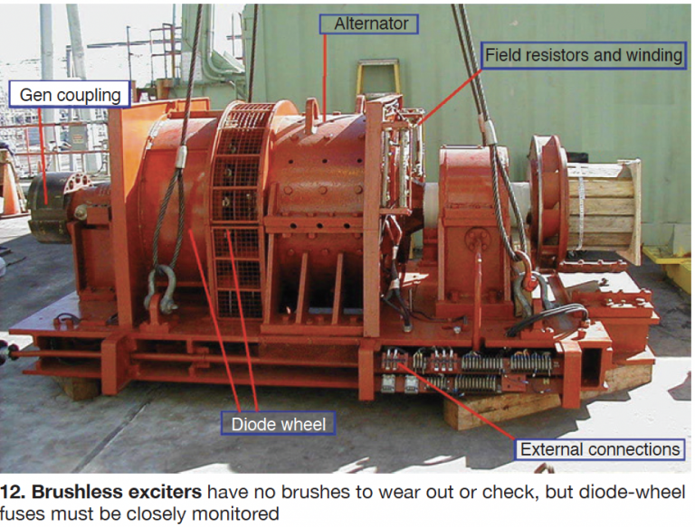
Demcko then described the types of excitation systems, using his decades of utility experience to review the pros and cons of each. Circuit diagrams and photos facilitate understanding of the technical material presented.
Static excitation has no rotating components, but collector rings and brushes are present and require close monitoring. Pros: (1) Very fast response, enhancing generator transient stability. (2) Can be made completely redundant up to the collector rings. (3) Simpler to understand and troubleshoot than a brushless system. (4) Field-ground detection systems also are simpler, and potentially more reliable than on brushless systems. Cons: Demcko identifies 10 cons—such as not being able to mix brush types and manufacturers—that make dealing with brush rigging and collector rings as much an art as it is a science. Access his presentation on the Power Users website at www.powerusers.org.
Brushless excitation pros:
- No brushes to wear out or check (Fig 12).
- No collector rings to fail, wear, or
- Reduced inspection and maintenance requirements.
- Less personnel exposure to dangerous
- Exciter power supply is immune to system voltage dips/sags compared to a bus-fed static

Cons:
- Complicated system to understand and
- Must closely monitor diode-wheel blown-fuse indicators.
- Limited redundancy (only in stationary elements).
- Field-ground detection systems more complicated and expensive than for static Usually slower performance than for an equivalent brushed exciter.
- Alternator maintenance can be expensive and require
- Forced outages can extend for periods longer than
Rotating alternator/dc generator excitation systems are discussed by Demcko to make his primer complete. But their day has passed, generally dating back half a century or more. The upgrade of some systems to modern digital regulators may have postponed a few retirements, but with the closing of ageing solid-fuel-fired fossil units this class of exciters is disappearing.
“Generator Copper Braze Joint Application Fundamentals, Neil Kilpatrick, GenMet LLC.
Neil Kilpatrick, a materials expert, opened his insightful presentation by acknowledging that copper braze joints are key to the successful performance of large generators. No argument there. Continuing, he said, “In the present day they provide high reliability and mostly maintenance- free operation.” No argument there either.
Then Kilpatrick hammered home the reason for his presentation: “This has not always been so over the history of large generators. This discussion on application fundamentals covers things that have been learned over the past 50 years or so.” Best practices and lessons learned regarding copper braze joints for gas- and water-cooled configurations is why you want to review Kilpatrick’s slides. Avoid remaking mistakes already corrected.
The challenge for electrical joints in large generators is that they must also serve as mechanical joints. While copper has outstanding electrical qualities, its structural capabilities are relatively poor. Kilpatrick walks you through the following:
- Braze-joint
- Braze-joint
- Braze-joint internal
- Hydrogen embrittlement of electrolytic tough pitch (EPT)
- Braze-joint failure modes and mechanisms—electrical overload/overheating, mechanical overload, and fatigue.


