HIGH-VOLTAGE ELECTRICAL EQUIPMENT
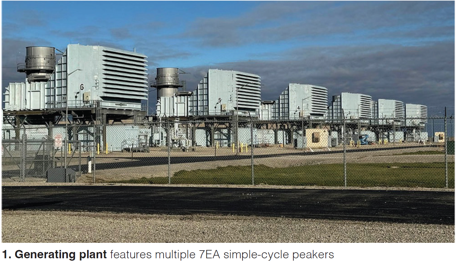
GE’s 7EA gas turbine is widely respected for its reliability, operational flexibility, and efficiency in simple-cycle, combined-cycle, and cogeneration systems, and mechanical-drive applications (Fig 1).
This frame has been upgraded and improved continuously since its introduction some three decades ago. Today, it is rated up to 90 MW in simple-cycle service. Combined cycles incorporating the 7EA (today often referred to as 7E.03 or simply 7E) can achieve an efficiency of more than 52%. With a focus on the future, the OEM says the machine is 100% hydrogen capable.
However, as Bruce Hack, a member of the management team at Crown Electric (CE) and National Breaker Services (NBS), pointed out at a recent industry meeting, “as is the case with any multi-component system, time has brought its weakest links near, or to, the end of their productive lives.”
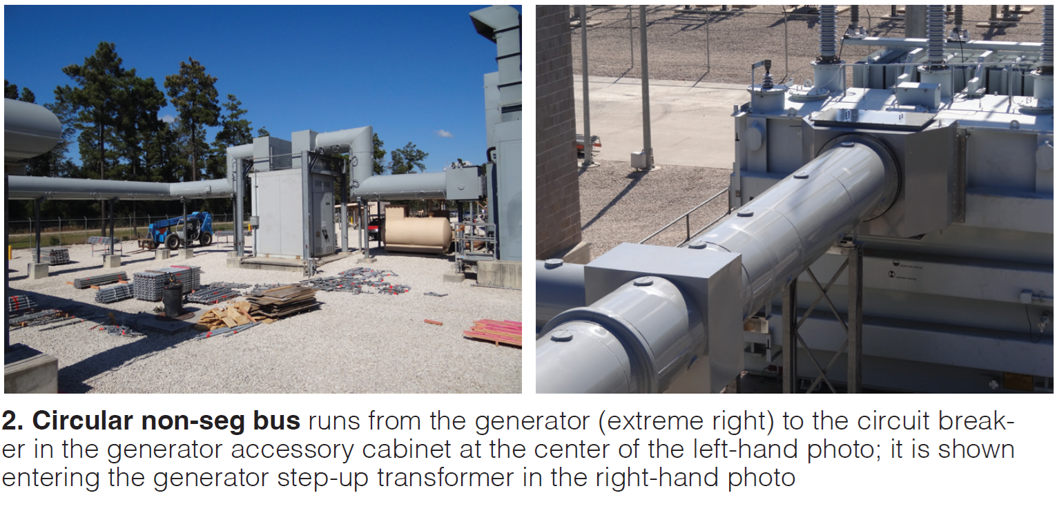
Two such sub-systems are (1) the main bus duct between the generator and the generator step-up transformer (GSU) and (2) the generator circuit breaker in the generator accessory cabinet (GAC) located in the middle of that run to protect equipment upstream and downstream (Fig 2). Industry experience indicates these breakers often were under-rated (and fraught with cooling issues) for the service duty encountered.
Hack told conference attendees that CE and NBS teamed up to provide a full turnkey removal and retrofill replacement of under-rated generator circuit breakers from GE (Magne-Blast) and PACS Industries. He said CE/NBS’s Citadel 5000-amp (fully rated) product is self-cooled and certified by KEMA Arnhem.
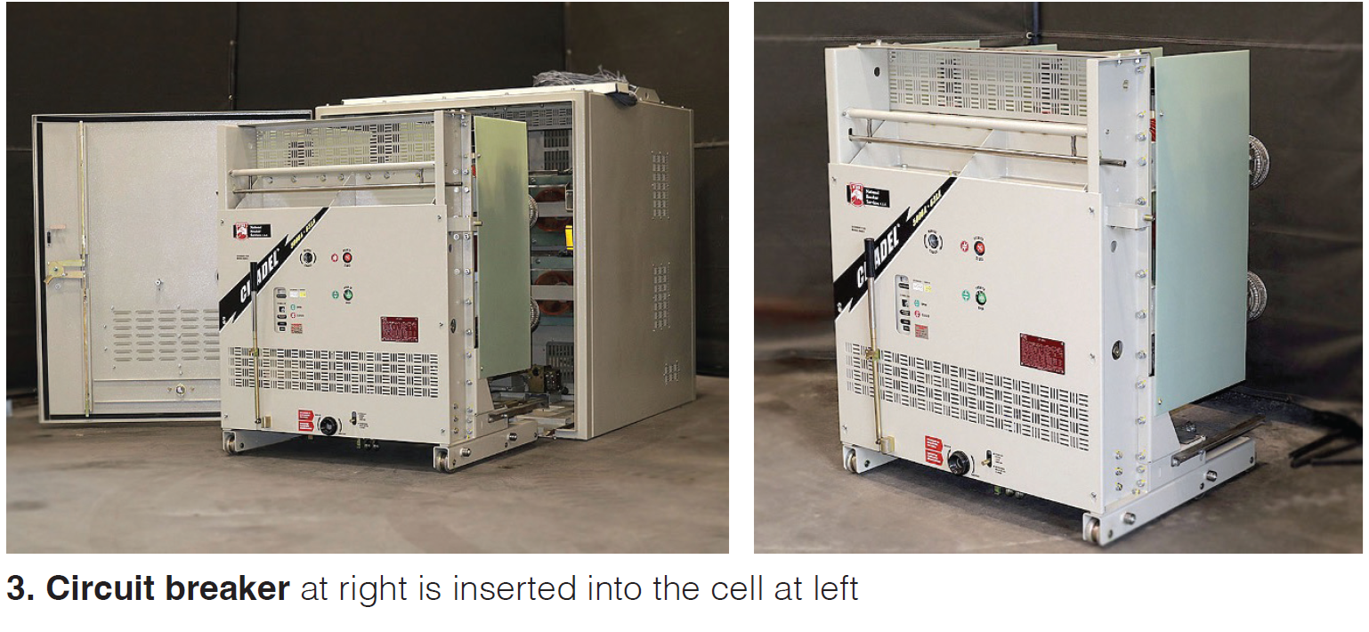
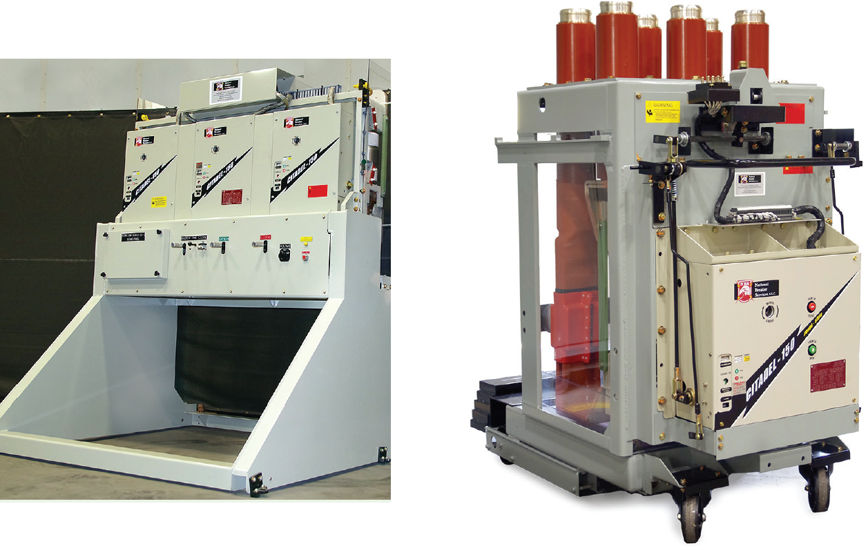
A few words on terminology are important here. The term cell refers to the “cabinet” shown at the left in Fig 3; the circuit breaker, which is inserted into the cell, is at the right. Retrofill is the removal of the original cell, its “guts,” and breaker, and their replacement—with a Citadel 5000 in this instance. Retrofit is used to describe replacement of the breaker only.
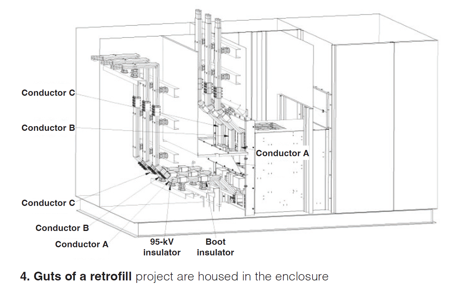
This is the way the retrofill process works: Upon contract execution, the plant shares with CE/NBS its available physical and electrical documentation (Fig 4). If CE/NBS does not already have these files in its library (from work at another plant), an outage for measurements is scheduled and Team CE/NBS visits the facility to take exact measurements and to verify the point-to-point wiring.
Critical measurements in hand, the CE/NBS design engineering team creates a retrofill kit package that perfectly overlays with (and can slide into) the space occupied by the original cell. These custom 5000-amp, 63-kA Citadel kits are sent to the site with everything from silver-plated copper to hardware to newly made bus boots.
Gutting and prepping of the original cell typically takes a day and a half. The original breaker is removed, of course, shutter assemblies too, and then the current transformers and their stationary primary disconnect bottles are taken out. The line load barrier is removed in whole or in part and modified during the installation phase as necessary (Fig 5).
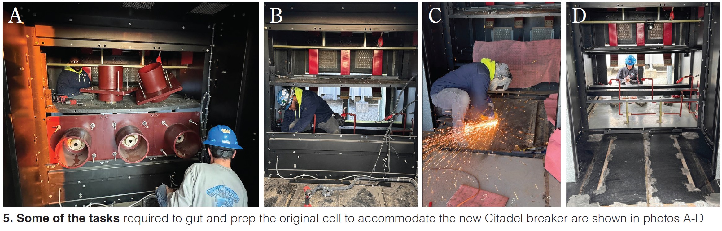
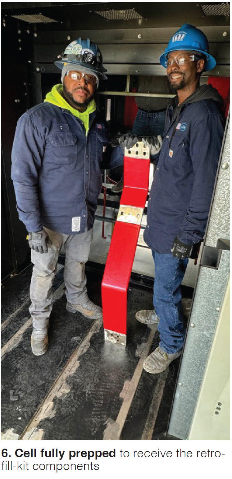
The six pieces of copper that connected the original cell to the line/load bus work are removed and replaced with custom copper to span the new topology. Floors and sidewalls are made smooth and safe. The fully cleaned and prepped cell is now ready to receive its retrofill kit components (Fig 6).
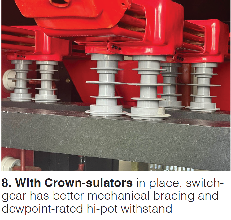
Inexpensive glastic stand-offs used in many of the original cells were associated with tracking and failure in 7EA bus duct and GACs industry-wide (Fig 7). Hack noted that CE had pioneered the development of so-called Crown-sulators—a bolt hole-for-bolt hole replacement for 95- to 150-kV BIL standoffs—and standard in all of the company’s retrofill kits.
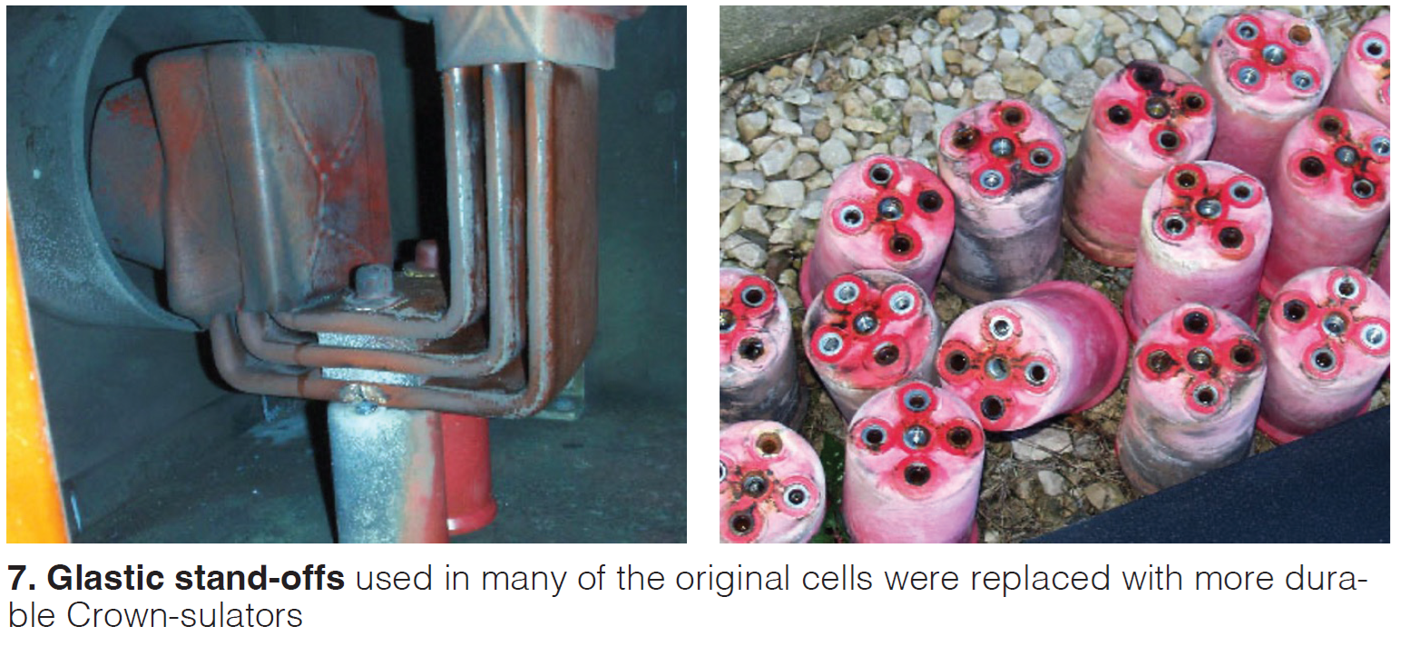
He said they have better cantilever strength, creep, and BIL characteristics than porcelain and are dew-point rated. Hack went on to say that with Crown-sulators in place, switchgear has better mechanical bracing and dewpoint-rated hi-pot withstand (Fig 8).
Mounting of the new bus and line load barriers normally takes a long day to a day and a half.
Options for owners of gas turbines other than the 7EA
National Breaker Services currently has three breaker options for gas-turbine owner/operators, with more on the way. One is rated 10,000 amps, the Citadel 5000 described in the text, and the Citadel 13.8-kV, 63 kA, 3000-5000 amps.
Cell installation is next. A 5000-amp, self-cooled Citadel cell is lifted into the space formerly occupied by the original cell in Fig 9. Once rigged into its precise location, the final bus connections are made and the line/load barrier is completed (Fig 10). Wiring is landed on the proper terminal-block points so control-room personnel can verify there is zero difference between the Citadel indications and those of the old circuit breaker (Fig 11).
Final installation step: The Citadel draw-out breaker is introduced to the GAC and its one-high enclosure (Fig 12).
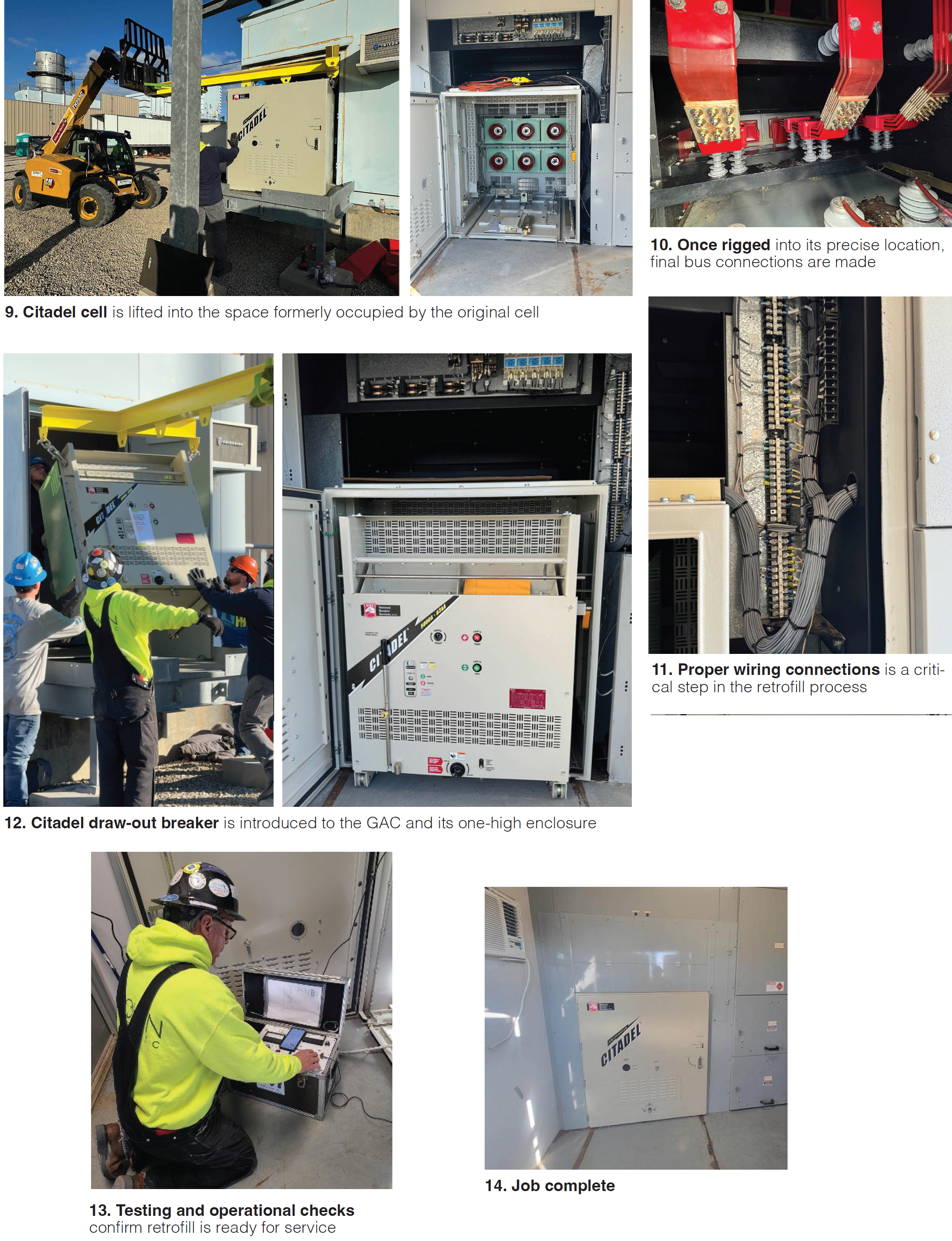 Completing the process. A full battery of tests (Fig 13), including operational checks, is performed by CE/NBS. After all tests are passed and documented, the cell’s flashing is installed to complete the retrofill installation (Fig 14). The entire retrofill process usually takes less than a week per position. Optional O&M training, offsite or onsite, is developed according to customer needs. CCJ