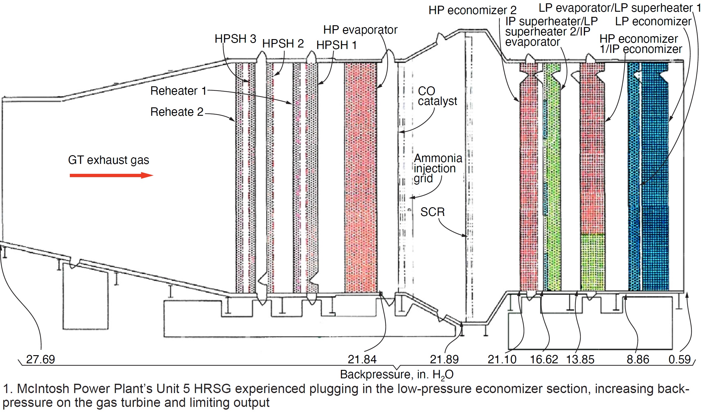
Maximum allowable duct pressure for the HRSG in Lakeland (Fla) Electric’s (LE) McIntosh Power Plant (MPP) Unit 5 combined cycle was 28 in. of water column (in. H₂O). After 20 years of operation, pluggage of the LP economizer in the Nooter Eriksen boiler caused high backpressure on the gas turbine/generator and limited its ability to operate at full load. High backpressure led to a derate of up to 14 MW. Cleaning of the economizer was ineffective in reducing backpressure because of HRSG design idiosyncrasies.
Multiple pressure transmitters were installed on Unit 5 for analysis of the pressure drop across the HRSG to understand when heat-transfer sections are experiencing pluggage and where to focus cleaning efforts during outages (Fig 1). In LE’s case, cleaning did not significantly change the ability to reach full load with an original alarm point of 24 in. H₂O and a runback set at 26 in.

Several modifications brought the allowable backpressure to 29 in. H₂O, with the alarm point reset to 27 in. and the runback to 30 in. Testing showed a significant efficiency gain by allowing Unit 5 to run up to the alarm point. At 27 in. H₂O, Unit 5 had an increase in output of 15 MW, eliminating the derate. Testing and analysis indicated the HRSG would require stiffeners in various locations to increase the design limit from 30 to 45 in.
An engineering firm was engaged to analyze the HRSG and to come up with an adequate solution to increase Unit 5’s allowable duct-pressure limits. The consultant recommended adding 245 stiffeners throughout the HRSG. Stiffener spacing, size, and design were evaluated using best engineering practices.
The engineering firm divided the required stiffeners into these two areas:
- HRSG inlet, reheaters 1 and 2 and HP superheaters 1, 2, and 3.
- HRSG outlet, the HP evaporator and remaining heat-transfer sections downstream to the exhaust stack.
For the first area, engineers evaluated casing stiffener spacing based on biaxial bending (plate theory) to accommodate a duct pressure of 45 in. H₂O. For the second area, stiffener spacing was based on large deflection/diaphragm stresses to accommodate a duct pressure of 45 in. H₂O; this evaluation was used as the basis for stiffener design.
The distinction between the two areas is based on experience that indicates the former should have more stiffening to avoid liner and pin problems as casing pressure is increased.
The design procedure used came from the fourth edition of Roark’s Table :X, which takes into account plate action when designing the casing for internal pressure. This analysis does not include finite-element analysis of the casing, but rather uses traditional mechanics of material theory. The initial design procedure relies exclusively on plant bending in two axes. Another approach is large deflection/diaphragm stresses. This approach recognizes the plate will resist the stresses in bending in both axes but there also is additional resistance—a membrane stress, or direct stress.
Testing and analysis showed Unit 5 had a significant improvement in efficiency and eliminated the derate load output by increasing the allowable duct pressure in the HRSG. To accomplish this, LE completed the following:
- Performed an engineering analysis of the HRSG to determine how many stiffeners and at what locations stiffeners would be required to accommodate an increase in duct pressure.
- Performed a test to show that increasing the duct-pressure limit would significantly improve Unit 5 efficiency by eliminating derates caused by pluggage.
- Added 245 stiffeners during an outage.
- Increased the operating backpressure limit to 27, 28.5, 29, and 29.3 in. H₂O for alarms and 30 in. for runback.
As a result of these improvements, guided by Todd Green, mechanical maintenance supervisor, and Jim Adams, electrical maintenance supervisor, Unit 5 is no longer derated because of HRSG pluggage and is able to make full load when required.
DIG DEEPER ON OCT 13 @ THE HRSG FORUM


