 As we prepare for the upcoming 7F Users Group annual conference in Atlanta, May 15-19, let’s take a look back at some of the most pertinent vendor presentations from last year, many of which will be updated and presented this year. Good to have some background details and foundational information of the non-OEM solutions for the 7F fleet, and undoubtedly, many other gas turbine models. Main focus here is generators and gas turbine upgrades.
Dig deeper
Presentations made at the 2022 7F Users Group meeting (and all other Power Users meetings) by owner/operators and vendors generally are available on the Power Users website. However, access is restricted to those who are registered on the Power Users Forum. To sign up, go to www.powerusers.org, and complete the form provided. It only takes a few minutes.
AGT Services
Jaime Clark kicked off the conference’s vendor presentations by addressing stator core looseness in gas- and steam-turbine generators. Perhaps to jolt the audience awake, even after breakfast and coffee, Clark noted that there’s a “huge uptick” in stator-related problems and later in his remarks quantified and expanded on his assertion: Generator emergent work during outages is up 30% in the industry for hydrogen-cooled units.
The litany of issues Clark addressed should make users quake in their boots until you realize that “the 7F generator fleet is 20-25 years old on average and the life of a stator is 20-25 years by design.” One big common phenomenon: The whole core gets longer after thousands of cycles, he explained; as you might suspect, peaking and load-following units are most affected.
Most of the looseness is compression-based, not related to vibration or thermal conditions, and “the problems are at the turbine end, not the collector end.”
Owner/operators of the MHI-built 7FH2s (in round numbers, 50 to 60 worldwide) perhaps should be quaking in their boots. These units are “losing teeth and failing,” Clark said, adding that MHI issues “can be catastrophic” and full stator rewinds are required. TIL-2260, which addresses these issues with MHI units, was revised in February 2021 to include findings from root-cause analyses.
Clark reported data on post-2260 repairs for six MHI turbine ends (TE) and TE coolers his shop was involved with, and found that two TEs were missing no iron, one was previously missing iron, and three with AGT repairs had no prior adverse reports or issues. Three of the TE coolers showed 100% looseness at the core outer diameter for the full length of the core, and presence of iron oxide at the inside and outside diameters. These units required belly-band tightening, stator re-wedge, and full core re-torque to 3000 ft-lb.
All GE 7FH2s will show signs of turbine-end iron looseness, Clark stated, and Model 324 units coupled to steam turbines are showing signs of outside space block (OSSB) migration (Fig 1). OSSB can cause a unit to “go to ground,” experience a phase fault, and melt iron and copper.
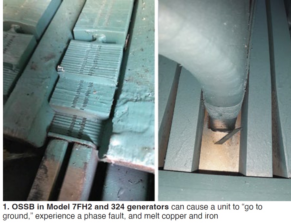
Why the OSSB issues? Clark explained it with three factors: (1) Axially loose core, predominantly on the turbine end, (2) poor bonding of OSSBs to core compression flange, and (3) after startups, the core expands radially and axially, tearing the “relatively thin” OSSB dovetail out at the key bar. On cool down, the core compression flange retracts but leaves the OSSB where it was. This repeats every operating cycle. Eventually, the OSSB cuts through the bottom filler and into the bottom bar groundwall insulation, resulting in a stator ground.
Viewing the photos Clark provides in his slides, along with additional material on repair strategies and causes of damage, will enhance your understanding of these issues.
Cutsforth
Jay Brennan and Chris Delavega described the company’s Insight CM condition monitoring software, which emerged from a broad program at major utility to develop new predictive technologies. Insight CM combines offline and online data on electromagnetic interference (EMI), electromagnetic signature analysis (EMSA), rotor flux, brush condition, shaft grounding (voltage and current readings), motor-current signature analysis, vibration, partial discharge, and thermal conditions to detect potential issues and avert failures.
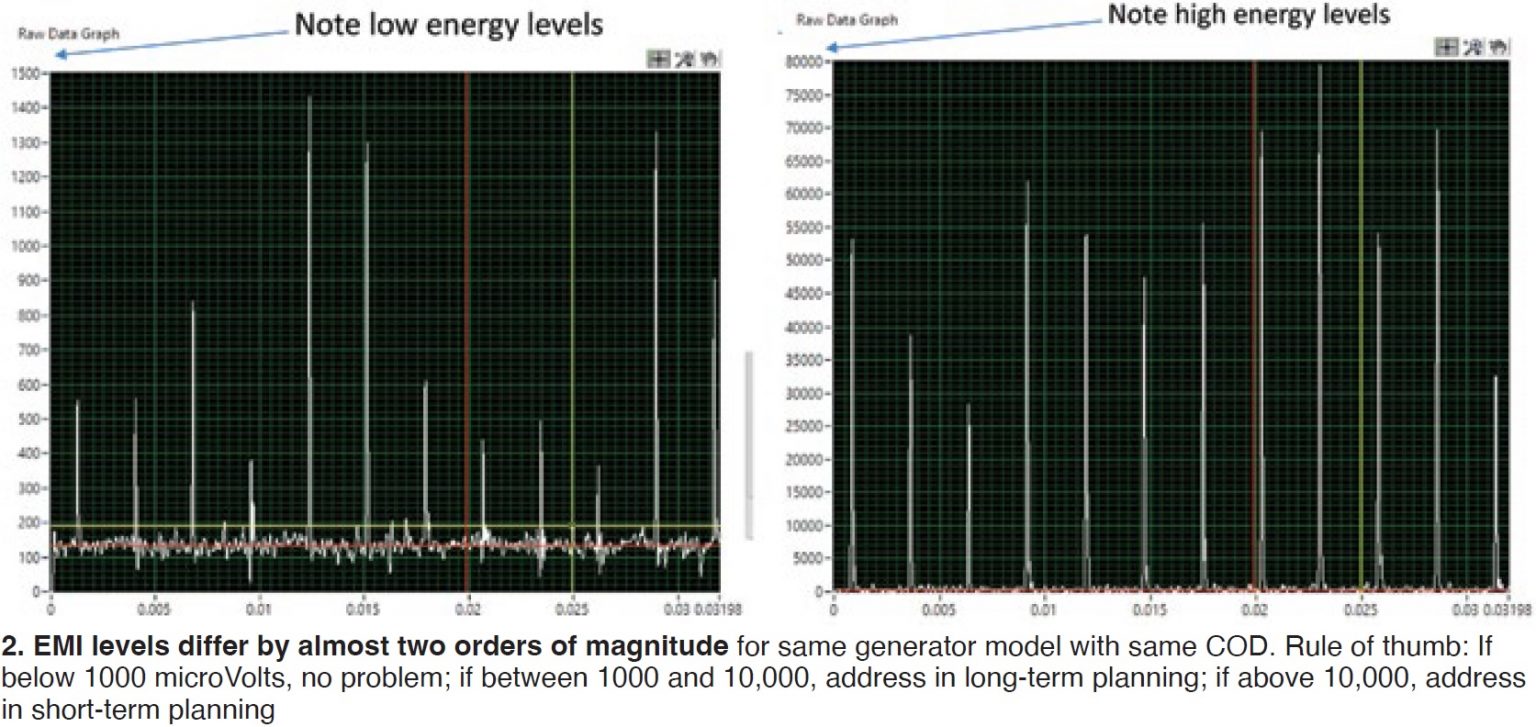
Different generators experience different issues as they age, even the same model with the same commercial operating date (COD), they said, evidenced in a case study (Fig 2) in which one generator showed micro-voltages under 10,000 while a sister unit showed “an order of magnitude difference.” The “bad sister” unit experienced a failure of slip-ring insulation.
In responding to questions, the pair noted that Insight CM collaborates with other data monitoring systems to include, for example, seasonal operating characteristics. Also, information from the Insight CM may lead a subject matter expert (SME) to investigate turbine mechanisms in seeking root causes of issues. The system does require a dedicated server.
National Electric Coil
Veteran user group expert Howard Moudy offered pointers on how to effectively rewind high-voltage generator stators, and referenced TILs 1211 (Hitachi units) and 2260 (MHI units). In most cases the stator core is reused, he said, the exception being MHI’s.
Issues addressed included looseness, dusting, greasing, and endwinding components of consolidated dry ties; endwinding vibration and resonance, in particular distinguishing between the two; and cracking of rigid phase leads at or near connections. He stressed the importance of staying out of the resonant exclusion zones when making repairs or replacements, 115-135 Hz for 60-Hz machines, 95-115 Hz for 50-Hz machines. NEC offers upgraded and redesigned components for stator rewinds.
Important details on each of these issues, repair mitigation strategies, are available in Moudy’s detailed slides.
Towards the end of his presentation, Moudy dwelled on “tangent delta testing” for dielectric dissipation factor on new stator bars and coils as a means of “identifying insulation issues.” Tan delta is an excellent differentiator of insulation quality, he claimed, and applies to “most insulation systems/processes applicable to 7F turbines,” although he also mentioned that including it in specs has met resistance in the industry.
A recent study revealed single-coil VPI (vacuum pressure impregnation) insulation systems for 7FH2 generators exhibited the best overall performance based on the Tan Delta Test and over 19,000 records. Other insulation systems/processes evaluated in the study were: Resin-rich vacuum treatment under hydrostatic pressure (RH), resin-rich pressed and cured in heated plate molds (RR), and global vacuum pressure impregnation (GVPI).
If tan delta is of interest, get hold of Standard 60034-27-3 issued by the IEC (International Electrical Commission), hailed by Moudy as “aggressive” on beneficial use of the method, The IEEE, he noted, is “getting there” but has not yet issued its own standard.
Gas Path Solutions
Michael Busack began by saying, “the next few years will be a battle of capital money vs work required in the industry,” but the implicit message perhaps was for users not to neglect more mundane components like those for the inlet filter house—replacement hoods, moisture separators (Fig 3), filters, flow meters, doors, and other hardware, plus evaporative-cooling media, which tends to “be ignored by plants.”

Filter hoods and frames are “the first things to fail” in the housing; Busack had several slides showing proper removal and replacement/installation of these key components. He also cautioned those who have upgraded the capability of their GTs that the filter grid can take only so much pressure before the tubesheet and support grids begin to deflect. Some dot 05 upgrades also require an additional air-filter module, he added.
Gas Path’s main business had been exhaust diffusers for 7Fs, but, in addition to filter housings, Busack listed inlet plenum expansion joint belts and inlet trash screens as other areas they can address for users.
Arnold Group
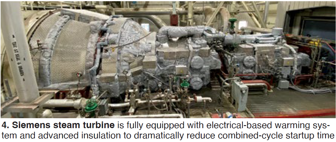
Norman Gagnon and Pierre Ansmann reviewed details of the company’s steam turbine warming and insulation systems which, among many other things, “can hold the turbine above the alarm setpoint temperature for 4.5 days or a 100-hour shutdown.” This keeps the unit ready for a warm start (see “Warming system, advanced insulation increase operating flexibility, reduce asset stress, cut costs.”
While most of the technical details are probably familiar to many user-conference attendees and best understood by first-timers through the pictorial offered in the slides, one piece of “news” offered by the duo is that Arnold is seeking beta sites to test its new HRSG drum warming technology.
Other bullet points of note:
- Among the many advantages of warming systems (Fig 4), include “babying” of aging turbines affected by bowing and/or vibration issues.
- While Arnold has active partnerships with several OEMs, the company “is tight” with GE; all H-class shell warming systems are supplied by Arnold.
- Removing and reinstalling the heating panels does not add to outage critical-path time because they are held on by only a few bolts and configured for easy removal and reinstall.
- The system does require its own electrical power distribution cabinet equipped with AC cooling, although the PLCs can be “built into” the plant control systems.
- Each heating panel has two cables for 100%, or duplex, redundancy.
- More than five dozen warming systems have been installed on gas and steam turbines over the last five years.
MD&A
James Joyce kicked off the Tuesday morning vendor presentations, addressing three topics important to owner/operators of 7FH2 generators: Spring migration, collector changeout, and flex link systems.
All styles of 7FH2s—Gen 1, Gen 2, Gen 3, and 324s—are affected by amortisseur spring axial movement under the body wedges of the generator rotor (addressed in TIL 2106), which can cause blockage of cooling air passages. If a whole row moves, Joyce added, it can halt cooling to all the rows. MD&A has a patented corrective repair, described as the insertion of a “top hat” which locks all the slots together so they can’t move, that can be done “with relative ease.”
Joyce then moved on to a case study of an onsite repair of a collector ring completely destroyed (without affecting field windings) by flashover induced by carbon buildup. The old deformed rings were removed, and replaced with new ones fabricated in the shop, keeping the bore copper sleeve intact. Users should visually inspect brushes for carbon buildup and remove it if found, then change the polarity.
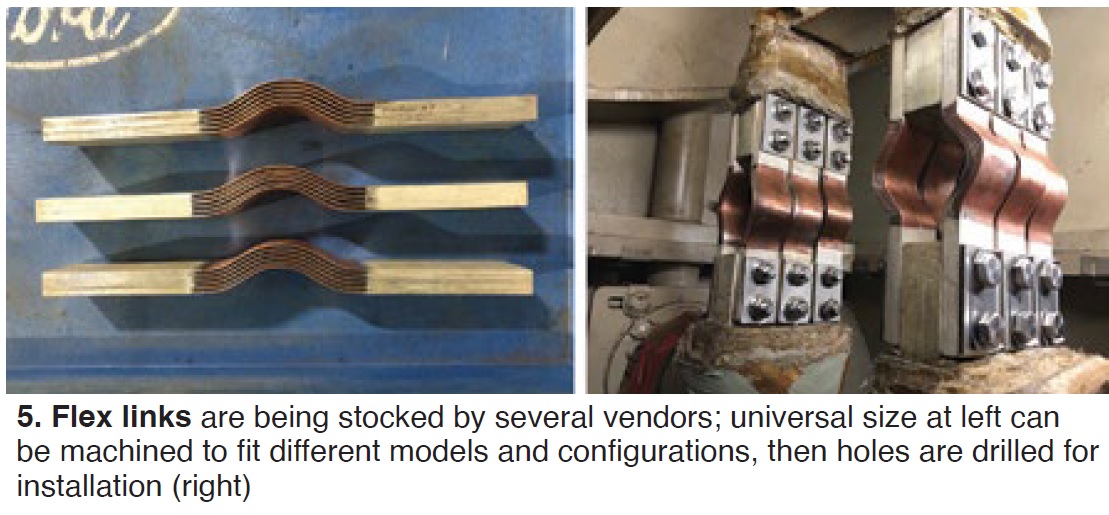
TIL 2106 also recommends visual inspection for cracking in flex-link connections (Fig 5) during an outage. There’s no standard borescope inspection technique for this, especially the bolt threads. MD&A (and others) stock pre-2014 and post-2014 (following an OEM mod) “universal-sized” flex links with “standard stainless-steel bolting.” Really old units may have to mitigate asbestos in the conforming putty. Electrical testing should be performed pre- and post-replacement, and users are encouraged to “change polarity, swapping wire leads, once every minor outage.”
JASC Controls
Schuyler McElrath described his company’s new, patent pending, Zero Emissions Equipment (ZEE) for achieving dual-fuel reliability, in other words operational testing of the liquid fuel system (LFS) without burning any fuel. ap4 is JASC’s partner on the technology, essentially a data acquisition, control, and flow simulation system along with a few new fluid handling components.
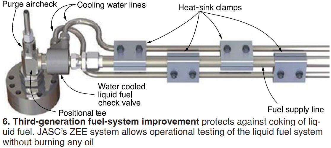
Water-cooled three-way purge valves (Fig 6), which combine functions of liquid fuel movement and purge air supply, are part of the package. JASC has been manufacturing and supplying these valves for years, so there’s nothing new or dramatic in the hardware.
Both firms are seeking a site for a demo. Sites in Texas and the Northeast are prime candidates because regulators there are urging a move back to dual-fuel capability for reliability when gas supply is choked off because of weather or other factors.
Unfortunately, noted McElrath, 7F turbines have unique system problems in the LFS, such as:
- The fuel stop valve does not seal in the reverse direction.
- Carbonization occurs when stagnant fuel is trapped in pipes that can reach 550F inside the casing, changing the fuel’s viscosity.
- The LFS deteriorates over time from water entrainment and corrosion.
- Fuel filters get damaged from leaking components.
- Users experience excessive fuel flow systems faults.
Water cooling these valves solves the coking/carbonization problem, said McElrath.
Koenig Engineering
Tim Connor essentially gave his audience a list of 10 maintenance items users should be aware of for the 900+ 7F aging gearboxes and turning-gear systems out there, over 90% of which are more than 20 years old. The list, and the percentage of units affected, included:
- Reducer output shaft lip seals, 100%.
- Hardened or cracked primary lip seals, 100%.
- Shaft grooves at lip-seal locations, 100%.
- Output coupling damage, 95%.
- Clutch output-shaft bearing wear, 90%.
- Clutch output-shaft grooves, 33%.
- Damaged clutch input components, 33%.
Doosan Turbomachinery Services
Jacob French, representing the rebranded Doosan Enerbility, first gave an overview of the company’s LaPorte (Tex) repair and overhaul facility, then proceeded to outline in detail the parts and services they can provide for 7F combustion-system inspections (CI), hot-gas-path (HGP) inspections, major inspections, and steam-turbine support.
Much of the presentation reviewed what HGPs, CIs, and majors require and when (in terms of total starts and hours), what they look for during inspections, and what typically they find – information likely well known to 7F user conference veterans, but perhaps useful to the 40+% first timers at this meeting. Check out the slides if you are in the latter category.
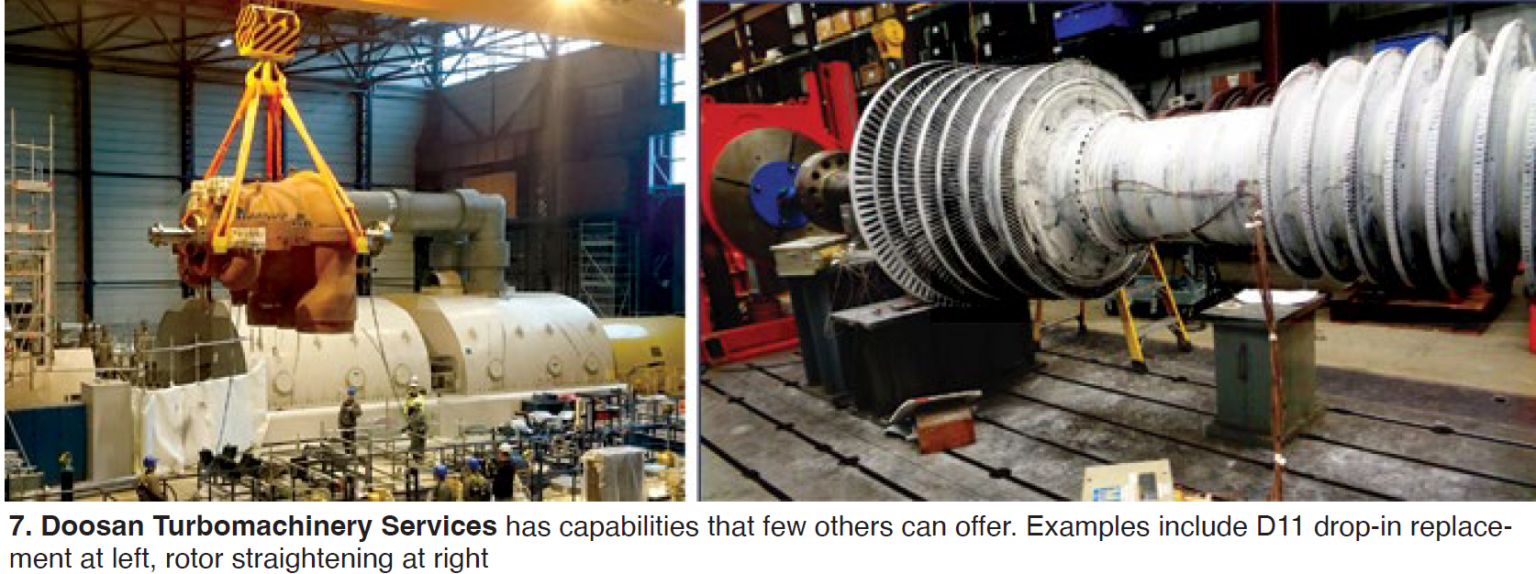
Doosan suggested here that users should keep “at least one spare gas-turbine rotor for your 7F fleet, as well as spare bearings and seals.” For steamers, the company offers a ‘full D11 drop-in solution with modern valve designs” (Fig 7) and other up-to-date components, many of which are also available through Doosan’s “Dart Parts” program.
Generally, GT services are available through the dot 04 model, although during the Q&A, the presenters did say they were “in the early stages of dot 04 bucket parts and service. An ominous note on the worldwide supply chain: Compressor through-bolts are available but it could take a year to deliver them to sites, even as the presenters recommended having at least two sets on hand.
 Turbine Controls & Excitation Group
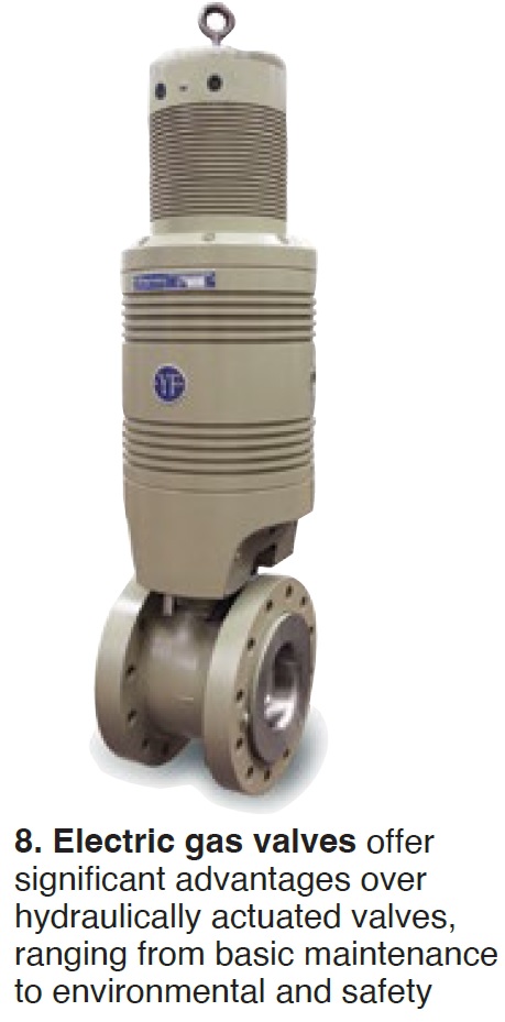
TC&E, part of ap4 Group, connected plant performance to instrumentation and valve issues, then urged listeners to conduct regular plant performance audits and establish a tracking system, keep instruments properly calibrated, and consider replacing hydraulic gas valves with electric models (Fig 8). The meme REAL, or reliability, efficiency/emissions, affordability, and longevity, was flashed several times to reinforce the message.
7F global fleet data suggest that 40% of the reported reliability issues could have been avoided with valve and instrument upgrades. I&C equipment failure events cause up to a week of downtime, up to $100,000/hr in lost revenue, and $10-50K of indirect costs per event. Global fleet data also suggest that moving to electric gas valves can extend maintenance intervals to 96,000 hours and reduce the risk of turbine trips.
The advantages of the GE-approved Parker Abex Jet-pipe servo valve, offered by TC&E for gas control, stop ratio control, and steam-turbine servo applications, were described to close out the presentation. Compared to the current OEM supplied valve, the Abex has a larger internal orifice size, reducing risk of plugging; larger second-stage spool diameter and surface area to keep it moving properly even if varnish builds up; and service life of five to six years compared to the 18-24 months of service life typical of the OEM’s valve.
I.A.F.D. Service Group
While IAFD offers engineering solutions to many plant components, material here was limited to liner plates (ducting between GT and HRSG and HRSG casing) and HRSG inspections. But first, the answers to a few trivia questions posed in the slides:
- A GE 7FA + HRSG has between 22,000 and 27,000 ft² of liner-plate surface area.
- Almost 800 “hardware setups” hold the round duct liner (between the GT and HRSG) to the casing.
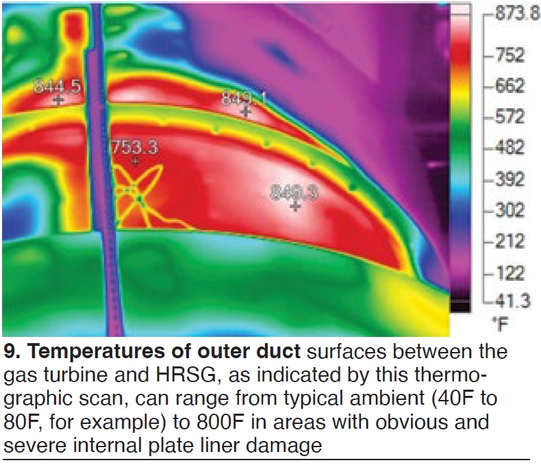
The graphics-rich presentation includes slides showing damaged internal liner areas, examples of non-uniform thermography (Fig 9) used to inspect for damage online, external discoloration revealing hot spots, broken internal retainers, and repair/upgrade photos. Upgrade options include increase quantity of studs for retention, uniform patterns for even distribution, compartmenting insulation on round ductwork, and over-insulating cavity space.
Two slides in the HRSG engineering section, also replete with photos, amount to a punch list of items to consider for both offline and online HRSG inspections.
Sulzer
Billy Bottera, superintendent for gas turbine rotors, divided his presentation thusly:
- A case study of how the Sulzer shop in La Porte, Tex, helped a customer get through an emergency rotor repair/upgrade situation (Fig 10).
- A detailed review of Sulzer’s shop and in-service capabilities, including a laundry list of repair techniques; coatings; rotor life inspections, assessments, and NDE; and the shop’s large rotor lifting and machining equipment.
The case study involved one of three simple-cycle 7FA+e must-run grid-support units at the customer site which was forced out of service and, upon borescope inspection, was found to have severe damage in compressor rows 14 through the EGV. Interestingly, the units are under an LTSA but the vendor could not deliver within the site’s time constraints of six weeks or less back in service.
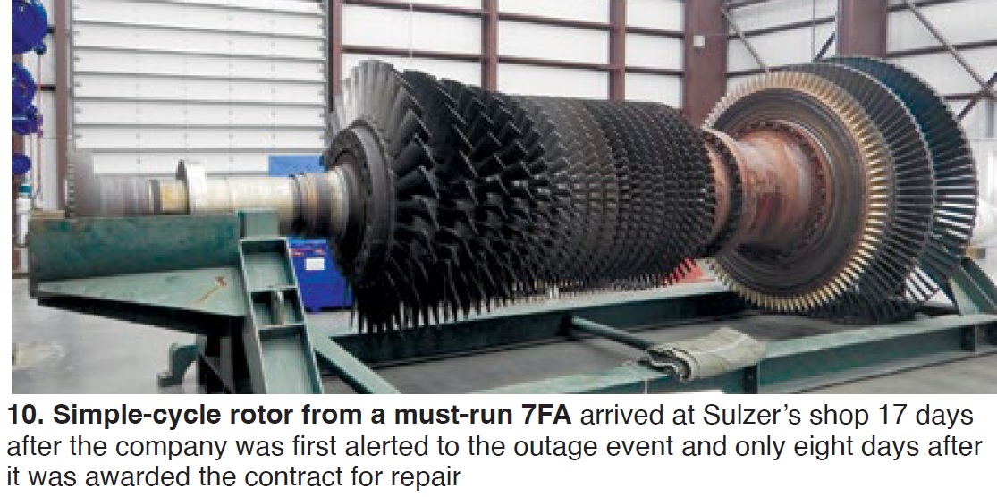
Sulzer inspected, evaluated, repaired, balanced, and prepped the unit for return within 36 days from when the rotor arrived at the shop. R17 hybrid design compressor blade/spacers were replaced with full robust root manufactured blades. R14-16 blades also were replaced with ones having robust roots. In addition, Sulzer was able to address emergent findings while remaining on schedule. All applicable TIL inspections were also accomplished—such as suitable contour, peen, and polish of R1 and R2 cooling slots.
PSM, a Hanwha company
Jeff Benoit, VP of clean energy solutions, laid out his company’s long-term strategy for reaching carbon-free gas-turbine combustion through progressively higher fractions of H2 firing. Parent Hanwha’s portfolio includes solar energy, electric energy storage, and site energy services, while PSM/Thomassen’s expertise lies in gas-turbine design and services. Expansion into H2 production, storage, and distribution represents future value-chain opportunity for the company.
The part of Benoit’s presentation likely of most interest to GT users, however, is PSM’s “HyFlex” high hydrogen combustion platforms, one of which is the company’s well-known FlameSheet™ combustion technology (Fig 11), which today is already capable of 60% H2 (by volume) firing while, says Benoit, maintaining less than 9 ppm NOx and CO, turndowns to 30% load, and 32,000-hr/1250 start maintenance intervals.
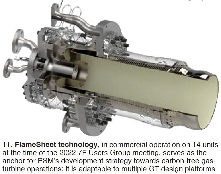
Prototyped in 2005, FlameSheet features novel flame stabilization techniques—such as four fuel circuits, two recirculation zones, trailing air injection to improve fuel/air mixing, low-differential-pressure combustor for improved heat rate and smaller footprint, high pre-mixer exit velocities for tolerance of highly reactive fuels (such as H2), and aerodynamic trapped vortex to ensure wide flame stability margin.
Latest projects include a FlameSheet-equipped Frame 7F firing up to 40% H2, scheduled for commissioning at the end of 2022, and a Frame 7E FlameSheet machine burning 50% H2 in 2023 for Kowepo, one of Korea’s top five power generation companies. PSM is also participating in the DOE’s Energy “Earthshot” program to drastically reduce the cost of H2 production and firing.


