Dean Motl called about the time of the spring equinox to say New Harquahala, the plant he manages, was inspecting P91 piping and found some off-spec material that he thought the industry might want to know about (sidebar).
Motl has benefited from collaboration with his peers in the 501G Users Group over the years and knows the value of sharing information. He mentioned soft pipe and the use of incorrect filler material on P91 welds as two issues identified. Also, that Maintenance Manager Chris Bates would be attending the upcoming HRSG User’s Group meeting (held April 12-14 in Jacksonville) and suggested that the editors meet with him to dig into some of the details. They did. Bates worked for a mechanical contractor when he learned first-hand about some of the problems associated with P91 – such as pipe cracking. He added to knowledge acquired on the job by speaking with industry colleagues and by attending HRSG User’s Group meetings.
When Bates transitioned from the mechanical contractor to New Harquahala a couple of years ago, one of the first things he did was ask questions concerning the paper trail on the plant’s P91. His experience suggested materials specs, heat-treatment reports, weld inspection reports, etc, often went missing. Another thing he had learned: A significant level of expertise was required to plan and conduct the proper metallurgical inspections and to analyze the data collected.
Some critical data needed to certify New Harquahala’s P91 piping as “meets today’s industry quality standards” was not available – just as Bates had thought. He championed the idea of conducting a comprehensive inspection program with the hope of recertifying the material installed.
Gaining experience in P91 inspection and analysis, and in developing inspection and testing guidelines, also would help others. NAES Corp, Issaquah, Wash, the plant’s contract operator and Bates’ employer, had perhaps another hundred plants under management that might also benefit from the lessons learned.
Due diligence of possible contractors for planning and conducting the requisite inspections and for analyzing the data pointed to Structural Integrity Associates Inc (SI, San Jose, Calif) as a company with significant and relevant P91 experience. SI was on NAES’s preferred vendor list and had done work at other plants the company manages so the decision to hire this consultant was relatively easy.
The editors also were familiar with SI’s work in the field having attended one of the company’s P91 workshops a couple of years ago. However, just how the firm acquired its expertise was an unknown until Fred DeGrooth and Steve Gressler, both of whom were involved in the New Harquahala project, offered the following backgrounder:
SI, a leading participant in EPRI (Electric Power Research Institute, Palo Alto, Calif) and international research efforts on P91, first identified material issues in 2000. One of SI’s clients was building a combined-cycle plant and had some questions regarding heat-treatment specifications. Inspection revealed off-spec material.
New Harquahala
That’s not a tongue-twister, merely a four-syllable plant name pronounced just the way it’s spelled. New Harquahala Generating Co LLC is located about 60 miles west of Phoenix in Tonopah. It is equipped with three natural-gas-fired 1 × 1 combined cycles power by Siemens Energy SGT6-6000G engines (formerly know as W501Gs). The plant, operated by NAES Corp, Issaquah, Wash, is managed by Dean Motl.
Another client, having suffered a fire at one of its plants, called in SI to see if the heat had adversely impacted the material. The firm again found off-spec material, but determined that the P91 softness (an indicator of substandard material) could not have been caused by the fire.
Not accepting the two findings of softness “a coincidence,” metallurgists immediately began developing an aggressive program to learn more about P91’s behavior and how to reliably and accurately identify material of poor quality. SI moved quickly to find any problems before warranties ran out.
Gressler said that an initial step in current P91 evaluation programs is to screen out the bad material. Specifically, eliminate the outliers – material that clearly has diminished properties. The current range of acceptable hardness for parent metal is 190 to 280 HB (Hardness, Brinell), he added, noting that the upper and lower limits have evolved over time. Weld hardness can be higher.
Hardness is only used for screening, Gressler continued. “Hardness by itself doesn’t determine material health, it’s merely an indicator.” Hardness doesn’t tell you when you’re going to have a problem and in that regard it’s much like your cholesterol level.
A baseline inspection is all-important. You must have current material properties to determine both a corrective course of action and how quickly the work must be done. But inspection is not as easy as it might appear.
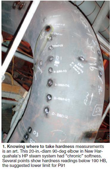
Knowing where to take the hardness measurements is an art, Gressler said, and data collection an iterative process. If you find some soft material, he added, you have to go back and take more measurements to see how large the affected area is, and how deep (Fig 1). Sometimes the softness is just at the surface in the decarburized layer and the base material is satisfactory.
New Harquahala’s strategy was to conduct its baseline inspection over a five-year period so most of the work could be done during regular planned outages and the project would have a manageable impact on the plant’s balance sheet. Bates said inspections focus on the high-pressure (HP) steam system from the heat-recovery steam generator to the steam turbine, and the hot-reheat (HRH) system from the HRSG reheater outlet to the inlet of the intermediate-pressure (IP) turbine section. All available drawings and materials and fabrication records for those systems were retrieved by plant personnel before SI began work.
An important step in the process was to prioritize which welds, fittings, and sections of pipe would be checked first, second, third, etc. SI prioritizes inspections based on a detailed review of plant design, procurement, and erection, using a method similar to the company’s Vindex™ method developed for lower-alloy piping. The Vulnerability Index is a semi-quantitative damage-ranking methodology that considers both inspection history and component characteristics. The damage consequences considered in Vindex methodology consist of safety and/or lost generation.
First year’s work. Inspections of New Harquahala piping spools and girth welds assigned Priority I status are scheduled for completion in 2010. Unit 2 was inspected early this year during a 45-day outage that included major compressor work. Next came Unit 1; work was completed during a 15-day outage scheduled for other purposes.
Some inspections have been done on Unit 3; remainder should be completed by year-end. Only about 10% of the piping in the HP and HRH systems was classified Priority I. Priority II and III each total about 30% of the P91; Priority IV represents the remainder.
Bates told the editors that the demanding Unit 2 outage absorbed all of the plant’s available manpower, leaving no one to work alongside SI on the metallurgical evaluation.
NAES considers the central engineering support it provides plant O&M teams a competitive advantage in business dealings. For the New Harquahala P91 evaluation, the company assigned Nancy Armstrong, a staff metallurgist located at corporate headquarters, to the plant for several weeks. That was an important move.
One reason: Armstrong’s experience. She has a solid background in the design of piping and pipe-support systems from her days as a component engineer at Ontario Power Generation Inc’s Pickering Nuclear Generating Station.
Another: Some inspection results were surprising and the knowledge Armstrong gained on the project enabled her to develop a set of best-practices guidelines on P91 inspection and testing to assist other plants in the NAES family.
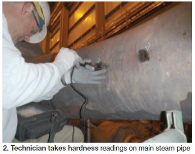
Positive material identification (PMI) and hardness tests were conducted on four HP steam and four HRH components and their respective girth welds. Low hardness values – approximately 170 HB – were found on two 90-deg bends and one tee on the HRH line (Fig 2). These anomalies suggested that in-depth testing was warranted.Unit 2, Phase I results
Metallurgical replicas were taken at representative test points and sent to SI’s Material Science Center in Austin, Tex. If analysis confirms the suspicion of metallurgists that the material has an improper microstructure – and by extension, reduced creep strength – further evaluation will be required.
This might include one or more of the following:
- Determine the depth of material softening by plug sampling and metallurgical analysis.
- Estimate future serviceability through engineering analysis conducted using conservative material properties in combination with actual design and operating conditions.
- Install high-temperature strain gauges to monitor strain accumulation. This would be done in combination with engineering analysis for life prediction.
- Replace the component.
DeGrooth and Gressler paused to stress the importance of proper microstructure in minimizing creep damage. They said that all materials suffer from creep in high-temperature environments, adding that creep-induced cracking of P91 has been found at several plants in the US and UK.
P91 accumulates creep and fatigue damage much like the older P22, which is more familiar to powerplant owner/operators. But because P91 piping has a thinner wall than P22 for equivalent service conditions it is less prone to thermal strains caused by temperature variations over time. Gressler said that an operating temperature of only 20 deg F above the design point can reduce material life by half.
Unexpected surprise
You may wonder why PMI testing is necessary. Perhaps you even think that it’s make-work for the consulting team. Consider this: Even if when all necessary drawings and materials certifications are available, do you really know if all the inspections that should have been done during construction (both at fabrication shops and in the field) actually were done, and how well they were done? Paranoia? Possibly. But lives may be at risk so you can’t afford to skip PMI in the inspection process.
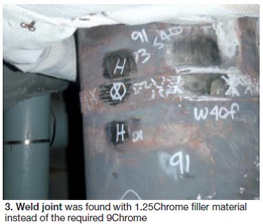
SI’s work at New Harquahala uncovered low-alloy filler material in a critical weld in Unit 2’s HP steam system (Fig 3). Then metallurgists found the same material in the same weld on both Units 1 and 3. Clearly, this was unexpected and of great concern. You can ask yourself, “Why did this happen? How did this happen?” But you’ll probably never know, and the only question that really matters is “How can we correct the situation, and how quickly must we react?”
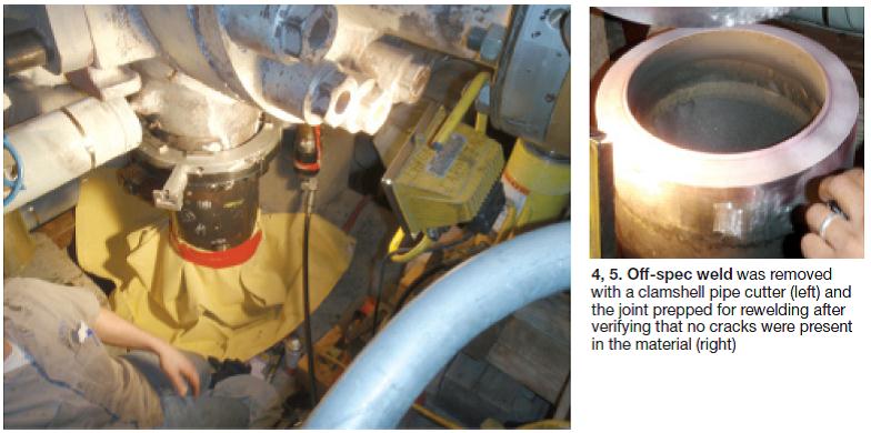
Background. PMI revealed that the circumferential girth weld joining the P91transition piece in the main steam line to the P91 steam-turbine stop valve was fabricated using 1.25Chrome material (P91 is 9Chrome). Decision: Replace the weld (Figs 4, 5).
The weld repair was not straight-forward because of the difficult location and the different sources of P91 material for the transition piece and the valve body. Regarding the latter, the valve, fabricated to European code standards, was tempered at a lower temperature than that used to temper P91 piping.
Documentation provided by Siemens Energy, which supplied the steam turbines as well as the gas turbines, indicated that for welds requiring heat treatment, the temperature range must be between 9 and 45 deg F below the last tempering temperature of the valve body: 1346F.
Industry experience indicates that exceeding the temperature can damage the base material during post-weld heat treatment (PWHT). However, the Siemens requirement is not consistent with guidelines presented in Section I of the 2009b ASME Boiler and Pressure Vessel Code, table PW-39, which recommends 1375F. But it does conform to the current version of ASME’s B31.1 Power Piping Code.
SI’s position was that the lower PWHT was acceptable but would require a significantly longer time at that temperature than it would at the higher temperature – specifically nine and a half hours at 1346F versus four hours at 1375F. Both the consultant and the plant thought this a reasonable compromise for achieving the required hardness while satisfying the Siemens request.
Hardness tests indicated a successful weld repair. All Brinell values were between 180 and 280 and full transformation to the desired tempered martensitic structure was achieved. More welcome news: There was no damage to the valve. Some softening of the pipe base metal occurred, mostly unavoidable given the extended PWHT soak time.
What might have been. Had the out-of-spec weld not been identified and repaired in a timely manner, failure was highly likely. What often occurs over time when materials of different chromium content are welded together: Cracks initiate and propagate through the carbon-depleted zone that forms during the welding process.
The “P91 Inspection and Testing Guidelines” prepared by Armstrong, based in large part on the New Harquahala experience, provides personnel at other plants managed by NAES a foundation in best practices for evaluating the metallurgical condition of material installed and for correcting deficiencies.P91 guidelines
The process suggested in the guidelines essentially follows the same path as that described above for New Harquahala:
- Gather materials tracking reports and inspection records.
- Collect records of material processing, induction bending, PWHT, etc.
- Conduct surveys of critical piping systems – including supports.
- Review stress analyses done by original designers
- Map HP and HRH steam systems and identify all components.
- Prioritize inspections and results.
- Identify inspection locations.
Next, Armstrong offered background on the approach generally taken when conducting P91 evaluations in the field – this to help plant personnel evaluate procedures proposed by companies bidding on inspection work. Three big caution flags before work begins:
1. Never conduct tests when a unit is running.
2. Make sure the steam supply system is isolated according to LOTO procedures.
3. Do not test piping when its temperature exceeds 100F and/or line pressure is greater than 2 psig.
The basic inspection approach:
- Verify material composition using x-ray fluorescence spectrometry.
- Map pipe-wall thickness prior to and following surface preparation at hardness test sites, both to confirm material removal to clean metal and that minimum wall thickness has been maintained.
- Map out locations for hardness measurements. They should extend around the pipe circumference at the 3, 6, 9, and 12 o’clock positions on both welds and base metal.
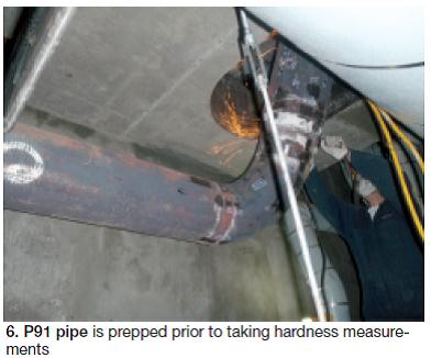
- Prepare locations by grinding only after a hot work permit is in place. A light disk grind of 5 mils or less generally is recommended, followed by use of a flapper wheel 120 grit (Fig 6).
- Test for hardness using the ultrasonic contact impedance method with supplemental testing using pin-Brinell.
- Accept hardness results in the acceptable range of 190 to 280 HB. If hardness is below 190 HB, disk grind 20 mils using a flapper wheel 120 grit to verify that the base material is soft and the hardness reading is not being influenced by surface scale. If the hardness is still low, and there is sufficient remaining wall to confirm that the material would not be compromised, examine further using replication or core or boat sample.
- Use metallurgical replication to examine microstructure at suspect locations.
- Site report should document the results and provide recommendations regarding any corrective action or additional testing.
- Nondestructive examination of the highest-priority weld location may include one or more of these methods: wet fluorescent magnetic particle, linear phased-array ultrasonics, and replication.
Once all the inspection data are collected and analyzed, Armstrong suggested development of a detailed plan both for future inspections and evaluations and for needed piping modifications. Other sections of the report detailed requirements and procedures for heat treatment, welding, and record-keeping. ccj


