Presentations made by MD&A, Shell Lubricant Solutions, ARNOLD Group, and EthosEnergy Group to owner/operators participating in Weeks Three and Four of the virtual STUG2020 conference are summarized below. You can access the recordings and PowerPoints on the Power Users website.
 MD&A: Using turbine performance to improve your maintenance strategy
 This presentation by James G Miller, PE, manager of performance services for MD&A, is a valuable primer for plant personnel participating in their first steam-turbine outage and equally valuable as a refresher for more experienced engineers and technicians. Miller’s message: Use the results of (1) recent performance tests conducted with the unit in service, and (2) steam-path audits made in the early stages of the outage, to reduce both outage cost and duration.
Miller reminded attendees that performance losses are a sign of degrading conditions that adversely impact the plant’s bottom line. The outage affords the opportunity to use this information for pursuing repairs and upgrades of greatest economic value.
The speaker covered the basics of performance testing, and how to conduct the all-important steam-path audit, in his presentation, which is available on the Power Users website complete with formulas, calculation examples, a comparison of as-tested performance to reference data, etc.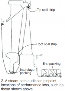
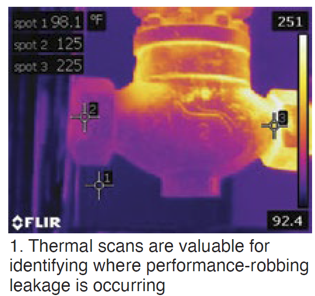
Best practices in performance testing—such a making sure there’s at least 25 deg F of superheat when calculating turbine efficiency—are included in the PowerPoint, together with a list of diagnostic parameters or additional tests that can be used to further characterize the sources of loss—such as solid particle erosion (SPE), casing leakage, and valve leakage. Thermal scans are particularly valuable for identifying the locations of leakage (Fig 1).
Examples of typical sources of performance loss identified during the steam-path audit include the following:
-
- Seal leakage (Fig 2).
- Surface roughness.
- Change in trailing-edge blade profile.
- Deposits.
Case studies identifying the reasons for performance loss in a reheat turbine at a combined-cycle plant, in a reheat turbine for a conventional steam plant, and in an industrial double-extraction condensing turbine are highly informative. For the first unit, performance testing revealed gross output had decreased by 2.3%. Excessive surface roughness, worn end packing, rubbed tip spill strips, and leakage by startup vents and HRSG drains were among the primary contributors to the loss.
A checklist of information to review in overhaul planning concluded the presentation.
Shell Lubricants: Choosing your lubricant not a one-size-fits-all
Lubricant selection is one of those subjects you might not think about for years, but when necessary it’s good to have a backgrounder like this at your fingertips—or only a couple of mouse clicks away on the Power Users website.
Key discussion topics include these:
-
- Base-stock evolution (Groups I through V).
- Varnish.
- Mitigation methods for varnish—including top-off fluids, filtration units, and fluid solutions (polyalkylene glycol, gas to liquid—lubricants made from natural gas).
- Field experience.
Varnish elimination with polyalkylene glycol (PAG) was a focal point of the Shell Lubricant Solutions presentation, which included a review of experience since 2001 at two units that switched to PAG to eliminate servo valve issues caused by varnish. Since then there have been no servo failures or trips while on PAG.
Recall that the stress experienced by a turbine lubricant contributes significantly to the ageing of petroleum oil, causing the non-polar fluid to oxidize. However, the resulting byproducts of decomposition are polar and insoluble in the base oil; they come out of the solution as varnish. Polyalkylene glycol, by contrast, is a polar fluid and, while it too oxidizes, the byproducts of decomposition are polar and infinitely soluble in the base stock. No varnish is produced.
ARNOLD Group: Advanced steam-turbine warming for increased startup flexibility
Pierre Ansmann opened his presentation on “the most advanced turbine insulation combined with a high-performance heating system to improve startup flexibility,” by summarizing its value proposition thusly:
-
- Increased in-market availability.
- Lower startup costs.
- Reduced thermal fatigue and longer mean time to repair for critical components.
- Increased operating flexibility.
He reviewed alternative warming-system arrangements, rejecting those integrating the heating circuits in insulation blankets, installing the heater on a thin mattress below the blanket, and using glass-fiber-insulated heating cable. The optimal system for the upper casing, they said, is heater on metal mesh baffle, for the lower casing, permanent mounting of heating cable below the split line.
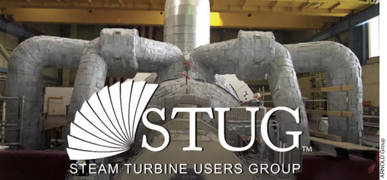
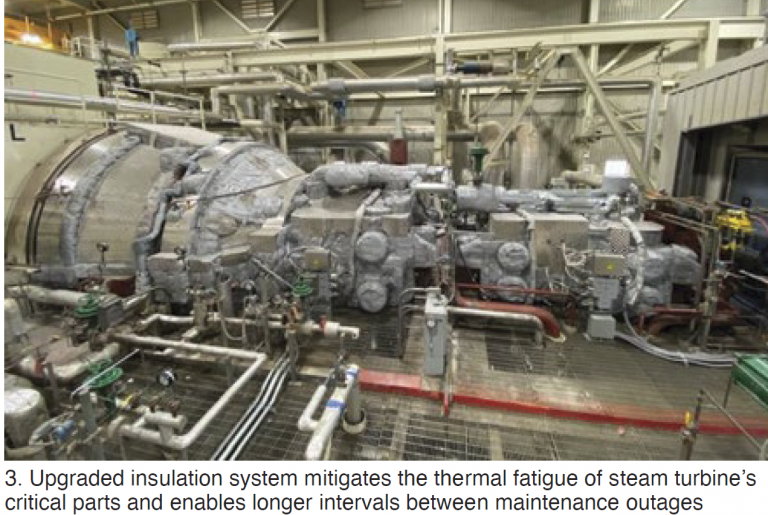
The ARNOLD system features interlocking high-performance blankets which conform perfectly to the turbine surface (Fig 3). High-quality materials and manufacturing, and long-term high-temperature resistance, allow the company to guarantee reuse of its insulation system for 15 outages without a decrease in efficiency.
Dozens of thermocouples, strategically located on the turbine, ensure proper heating. Each of the 18 or so heating zones has t/cs installed on the heating wires to double check if the zone is responding correctly and at the specified temperature. Below every heating zone, multiple t/cs are mounted on the casing to confirm even heating of the turbine.
Ansmann said a properly maintained ARNOLD insulation system can maintain your turbine in a hot-start condition for at least four or five days after shutdown. No preheating of the turbine is required prior to a start within this time period, reducing startup fuel consumption and auxiliary power.
Combining high-quality insulation and warming systems enables tight control of casing-to-casing and rotor-to-casing expansion during shutdowns. A goal for operations personnel to aim for, Ansmann said, is a homogeneous cooldown to maintain the temperature difference between the upper and lower casings to less than about 100 deg F. Access the recording and slides here.
EthosEnergy Group: Multiple upgrades improve D11 reliability
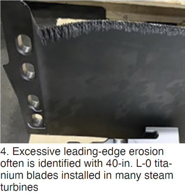 Owner/operators of the popular D11 steam turbine are sure to benefit from a review of this illustration-rich, 50+ slide presentation, easy to access the recording and hard copy in the Power Users archives. The presenters from EthosEnergy cover the repair of 40-in. L-0 blades, and upgrades of Smart seals and the N2 packing box, among other things. The subject plant was a 4 × 2, 1240-MW combined cycle. COD for the unit upgraded was 2011; first major inspection in 2020.
Two rows of the damage-prone L-0 blades were weld-repaired prior to the outage to correct excessive leading-edge erosion (Fig 4). Cracking in the blade pin-finger dovetail roots also was addressed. Presentation provides details likely of value to anyone facing the same issues. Photos illustrate key steps in the process, including re-blading of the L-0 row.
The Smart seal upgrade was done to address rotor vibration caused by seal rubs. Experienced users know the HP/IP rotor is very flexible and sensitive to mid-span rubs. Detailed measurements of packing and tip-seal wear (average horizontal, top, and bottom) are presented. Heaviest rubs are identified with the lower-half horizontal joint. The speaker noted that although clearances generally are larger on the bottom, wear is substantial at all locations.
A seal developed to upgrade OEM seals to avoid rubs and wear during startup and shutdown, by way of additional clearance, is illustrated. Reduced vibration during startup is one benefit. Another is increased revenue, said to be upwards of $17-million for a typical 300-MW steamer over an eight-year run time. Information on estimated savings in fuel and carbon emissions also are presented.
N2 packing heads, which contain shaft seals between the HP and IP steam paths, have a history of horizontal joint leakage. This impacts performance because HP inlet steam leaks into the IP section. Plus, steam cutting occurs across the horizontal joint. The presenter highlights what his company’s experts say are design issues that prevent maintaining a closed joint. Described modifications are said to mitigate the problem.


