“Steam Turbine Repair Planning and Execution,” Bryan Grant, Advanced Turbine Support LLC.
Whether you inspect/repair your plant’s steam turbine or contract out those services, Bryan Grant’s presentation is a valuable reference for O&M personnel, one possibly worthwhile reviewing ahead of your ST inspection/maintenance outages. It’s available on the Power Users website 24/7.
Grant offers tips on repair planning, blade replacement, J-seal installation, when to repair/when to replace nozzles, and final inspections. Plus, he stresses the importance of final FME (foreign material exclusion) close-out inspections prior to unit closure.
One of the speaker’s messages: Be prepared, especially when finger dovetail replacements are involved. Some of the retention pins will hang up during removal, he explained, but most can be persuaded to come out with a hilte or peening gun. Those that remain often must be machined out. This can be a risky operation because it’s easy to damage dovetails.
Risk mitigation during finger dovetail installs demands close attention be paid to the availability of parts and reamers. This entails verifying the sizes of pin holes as designed and to be aware of any oversize holes identified during previous outages. Grant said the lead time for the all-important reamers is upwards of about two months. How many should you order? His rule of thumb is to restrict reamer use to 20 holes. When reinstalling pins, he continued, start at the bottom hole and work your way up.
J seals received significant air time. Not every turbine has them, and all J-seal designs are not the same, Grant went on. Inspections for straightness and crush checks were described. Make sure the J seals are installed correctly with respect to steam flow, he noted. If installed backwards the steam flow acts to pull out the seal. Remember, you want a small gap where the two hemispherical sections of the J straps meet. Photos in the slides show what to look for during J-strap inspections.
Regarding hardware inspections, Grant urged attendees to replace: Never reuse old hardware. Photos described the proper procedure for conducting balance-weight and L-0 mid-span inspections. Staking of balance weights was said to be “incredibly important” to assure weights do not escape during operation. Decisions on diaphragm repair versus replace also were illustrated by way of photos.
“Fluid Film Bearing Visualization,” Dr Lyle A Branagan, Pioneer Motor Bearing Co.
Lyle Branagan is a familiar face/voice at user-group meetings in person and online. His well-illustrated presentations typically cover the design basics of journal and thrust bearings for motors and gas and steam turbine/generators, materials, lubricants and lubrication systems, machine dynamics and performance, installation/operation/maintenance, the importance of quality control, etc.
If you’re new to the business of power generation, listening to or thumbing through the slides in one of Branagan’s presentations is a good way to get introduced to bearings. If you’ve been on the deck plates for several years and haven’t been exposed to bearing work recently, his PowerPoints and videos are a good refresher.
Branagan’s presentation before the 2019 STUG meeting is available in the Power Users library, a video of his 2020 7F Users Group presentation can be accessed at Power Users and in CCJ’s webinar library.
“Failure Modes for Hydraulic Components and Control-Valve Actuators for Steam- and Gas-Turbine Applications and Strategies to Mitigate,” Ralf Bentfeldt and Tom LaCombe, Rexroth, a Bosch company.
This is another presentation available on the Power Users website that you might want to link to for your personal library of troubleshooting best practices. Valve actuators typically are an afterthought until they suffer an operational hiccup or must be removed for inspection and maintenance. [link to article] That probably doesn’t happen more than once a year, so it can be difficult to remember everything you should.
The speakers mentioned that 70% of hydraulic-component replacements are attributed to surface degradation—from abrasive, erosive, adhesive, and fatigue wear—and that 71% of these causes of mechanical wear can be associated directly with hydraulic-fluid condition. That means they are within the user’s ability to monitor and control.
Common fluid issues impacting mechanical wear of hydraulic components are temperature and viscosity, water ingression, air entrainment/cavitation, and contamination. The presenters cover each of these mechanisms individually, offering best practices and rules of thumb to improve outcomes on the deck plates. Example: One chart that illustrates the impact of low viscosity on component wear and the optimal fluid temperature to minimize physical contact between internal parts.
“Benefits of an Alternative Material for In-situ Hardfacing of Valve Seats,” Joerg Schoepp, Power Service Group.
Cobalt chromium hardfacing alloys 6 and 21 have been used to overlay high-wear components—such as steam-turbine valve seats—for decades, protecting against oxidation, impact damage (valve closing), solid-particle erosion, and friction-related wear. Industry requirements that valves be fast-acting while operating at temperatures approaching 1100F in some plants are linked to delamination of the CoCr layer from the high-chrome (9% to 12%) base material. Liberated metal causes downstream damage to components in the steam path.
A buffer layer between the base material and hardfacing has worked in some cases, but it creates additional steps in manufacturing and refurbishment of valve seats, increasing both cost and time. Plus, some recent valve designs have the added complexity of seats that cannot be removed for refurbishment, dictating in-situ seat replacement. Several slides provide key steps for in-situ seat replacement (photos are included) and attest to the challenges of hardfacing in the field.
Joerg Schoepp speaks to the company’s positive experience in using a single layer of Inco 625 for valve seat protection. By eliminating the buffer layer, the company’s general manager of repair services says, “greatly reduces outage duration and variability” while also mitigating the risk of the hardfacing layer to liberate from the base material.
“Technical Considerations for Optimizing Steam Turbine Startups,” Matthew P Scoffone and Thomas R Reid, PE, TG Advisers Inc.
The consultants consider both vintage and modern steam turbines in their presentation. Regarding the former, they identify the following as possible impediments to faster starting for economic benefit: HP/IP creep and embrittlement concerns, solid particle erosion, rotor bow, and casing cracking; for the LP section, stress corrosion cracking and water-droplet erosion.
Modern and retrofit steam turbines are characterized by less accumulated fatigue damage, a more aggressive duty cycle (cycling service, for example), turbine inlet steam temperatures of 1050F and higher.
The presentation [link] offers insights on how vintage rotors age, the importance of correct hold speeds, pre-warm to reduce the mismatch of steam and metal temperatures, clearance considerations for cycling, and startup modifications.
The presenters assure that opportunities exist to safely reduce cold start times without capital upgrades. They are identified by use of recent inspection results, finite-element analysis, and modern fracture mechanics principles. In their experience, cold-start times on legacy turbines typically can be reduced by 25% to 50% while still adhering to critical OEM design parameters and requirements.
“Fundamentals of Steam-Turbine Valve Maintenance,” Mark A Cohen and Scott Cavendish, PE, Independent Turbine Consulting LLC.
Mark Cohen and Scott Cavendish dig into the details of steam-turbine valve maintenance, touching on valve sticking and oxide management, in-service monitoring of valves, extending maintenance intervals, balance-chamber failures, and valve actuators. The presentation is heavily illustrated with meaningful photos. For example, the photos of valve oxide and stuck valves were taken immediately after valve outages where the oxide was not properly removed and the valves had to be taken apart again to correct the failed attempt.
Cohen, a hands-on maintenance expert who probably has forgotten more than many have learned in their careers, is an engaging bareknuckle speaker who maintains your attention with a seemingly inexhaustible supply of anecdotal case histories. Thus, the formal presentation posted on the Power Users website doesn’t cover all that he shared at the meeting. If Cohen presents at the upcoming virtual 2020 STUG conference starting November 11 be sure to tune in.
Restoring design clearances to original dimensions was the first topic. The speakers said 80% of valve sticking incidents is traced to incorrect high-temperature oxide maintenance—such as not honing and using try-bar go/no-go checks. Attendees were warned that grit blasting does not remove oxide, it only polishes surfaces. Reason: Oxide deposits are harder than the grit. When asked about the proper valve maintenance interval, Cohen said it depends on the oxide growth rate. Scale, he continued, is like bark on a tree: It keeps growing until you remove it.
He stressed that oxide removal to bare metal is tough hand work typically using nominal 60-grit bricks; higher doesn’t work, Cohen assured. A couple more best practices shared:
-
- Never change a part unless it really must be changed because you could make an error in replacement and make a good thing bad.
- On bolting up valve connections, stud tightening must be done until you see sealant squeeze out. Leaks on 1960s machines that never existed previously, it was said, testify to today’s lax work procedures.
- In-service operational monitoring can detect only stuck valve, not insufficient clearances caused by oxide buildup.
“Don’t Do That to My Steam Turbine” was the second part of the presentation by Cohen and Cavendish. It focused on operating procedures to avoid turbine damage, including the following:
-
- Adhere to starting and loading temperature matching to minimize life expenditure and avoid cracked shells and distortion of hot parts. Remember that metallurgical life cannot be restored. Example: Cracked shells cannot be fully repaired back to new metallurgy, only temporarily patched. And when shells are patched it’s even more important to temperature-match.
- Quenching during an improper shutdown causes the most damage; it puts metal surface in tension. During shutdowns, avoid low/no-load operation with a hot rotor. On a hot restart, avoid quenching hot parts.
An example of quenching damage to valve parts was presented. Boiler producing 1000F steam tripped with a resultant drop in steam temperature to 750F-800F. Inspection revealed cracking to three valve seats and stems. Keep in mind that the differential expansion of stellite is twice that of the base material.
Some podium time was dedicated to turbine layup and the corrosion damage and stress corrosion that can result if proper procedures are not followed. Avoid moisture entry into the casing and oxygen-induced corrosion with dehumidification, inert gas and sealed casings, heat, and covered storage, the group was told. Periodic rotor rotation and filming amines were among the suggested actions.
“Advanced Single-Layer Turbine Warming System Improves Startup Flexibility,” Pierre Ansmann and Norman Gagnon, ARNOLD Group.
Pierre Ansmann and Norm Gagnon opened their presentation on “the most advanced turbine insulation combined with a high-performance heating system to improve startup flexibility,” by summarizing its value proposition thusly:
-
- Increased in-market availability.
- Lower startup costs.
- Reduced thermal fatigue and longer mean time to repair for critical components.
- Increased operating flexibility.
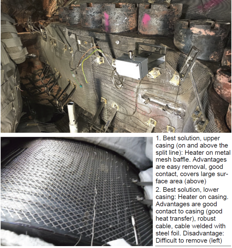
The duo reviewed the different warming-system arrangements, rejecting those integrating the heating circuits in insulation blankets, installing the heater on a thin mattress below the blanket, and using gas-fiber-insulated heating cable. The optimal system for the upper casing, they said, is heater on metal mesh baffle (Fig 1), for the lower casing, permanent mounting of heating cable below the split line (Fig 2).

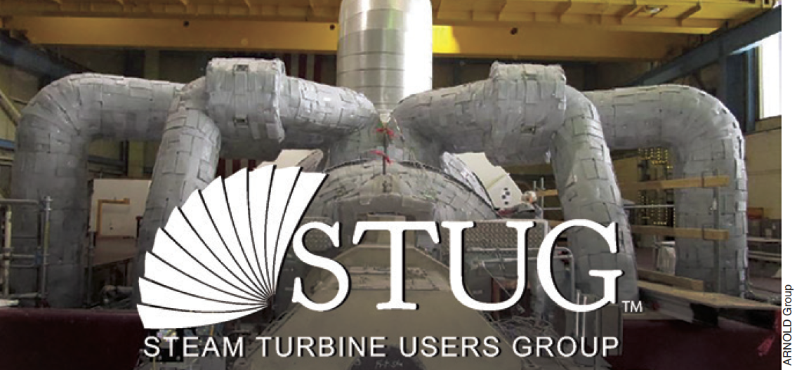
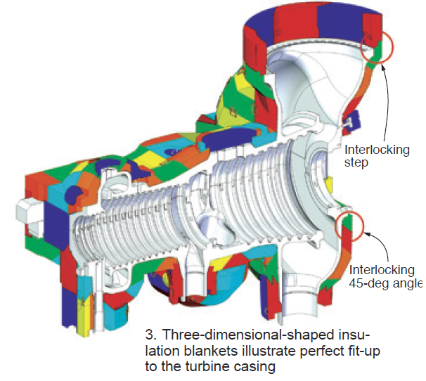
 The ARNOLD system features interlocking high-performance blankets which conform perfectly to the turbine surface as shown in Fig 3. High-quality materials and manufacturing, and long-term high-temperature resistance, allow the company to guarantee reuse of its insulation system for 15 outages without a decrease in efficiency. The insulation system for a 330-MW GE steam turbine is on the first page, integrated with the STUG logo.
More than five-dozen thermocouples, strategically located on the turbine, ensure proper heating. Each of the 18 or so heating zones has t/cs installed on the heating wires to double check if the zone is responding correctly and at the specified temperature. Below every heating zone, multiple t/cs are mounted on the casing to confirm even heating of the turbine.
Ansmann and Gagnon say the ARNOLD warming system can maintain your turbine in a hot-start condition for at least four or five days after shutdown. No preheating of the turbine is required prior to a start within this time period, reducing startup fuel consumption and auxiliary power.
To learn more about ARNOLD’s control system and blanket design, plus, how company technicians would go about custom-designing an insulation system for your steamer, be sure to tune into their 60-minute presentation at the upcoming STUG 2020 Digital Conference on December 9.


