
The annual conference of the Steam Turbine Users Group is being conducted online for the first time this year. The four-week event, exclusive to owner/operators, began November 11 with a program focused on user experiences and vendor presentations. The latter were limited to 30 minutes each and conducted in two half-hour sessions. Each vendor was assigned a “breakout room” and users were connected to their presentations of choice. While attendees could not participate in more than two vendor presentations during the live Week One program, all presentations—both user and vendor—are available now on the Power Users website.
Highlights of the Week One user and vendor presentations, developed by the editors, are below.
Week Two was GE Week, characterized by meaningful technical presentations, Q&A, and open discussion on topics of interest to the user community. Those presentations can be accessed through the OEM’s MyDashboard website.
Week Three’s program begins on Wednesday, December, 2 at 9 a.m. Eastern with the first three hours allocated for private meetings with vendors; schedule these online just as you would a doctor’s appointment. Presentations by users are next, from noon to 2 p.m. followed by these two hour-long live vendor presentations with Q&A:
-
- MD&A, 2 p.m., “Using Turbine Performance to Improve your Maintenance Strategy.”
- Shell Lubricants, 3 p.m., “Choosing and Maintaining Lubricants for your Steam Turbines.”
- A virtual vendor fair, complete with video chat rooms, runs from 4 p.m. until the end of the day’s program at 5.
STUG2020 concludes with the Week Four program on December 9. Program format is the same as that for December 2. The featured vendor presentations on the last day of the conference are these:
-
- Arnold Group, 2 p.m., “Advanced Steam Turbine Warming for Increased Startup Flexibility.”
- EthosEnergy Group, 3 p.m. “Multiple Upgrades Improve Reliability of a D11.”
STUG2020, Week One user presentations
“D11 Last-Stage-Bucket Inspections and Findings” at five plants suggests that leading- and trailing-edge erosion of L-0 blades is driven by operating hours and exhaust temperature versus starts. More specifically: The fewer the hours and the higher the temperature the less erosion. Inspections indicate that stellite shielding noticeably reduces the erosion rate, moisture-removal troughs in the last-stage diaphragm do as well.
Other findings are the following:
-
- Erosion rate for combined-cycle turbines is higher than for steamers at coal-fired plants, in most cases. Plus, trailing-edge erosion is more prevalent in the combined-cycle fleet.
- Erosion proceeds quickly after COD, then slows. Thus, if you blend out surface irregularities, the airfoils actually erode faster than they would have had you left them alone.
- The highest level of erosion typically occurs from the top of the blade to 3 in. below it.
- Blade damage is related to the moisture content of the steam more so than water chemistry.
Experience with 40-in. titanium L-0 blades—Case History One. Owner/operators of Toshiba steam turbine/generators received an alert in fall 2018 regarding the failure of 40-in. titanium L-0 blades at a Japanese powerplant. The OEM recommended inspections every 24k operating hours or 600 starts.
Personnel from a US combined-cycle plant with two steam turbine/generators affected by the notification shared with STUG2020 attendees their inspection and repair experiences from spring 2018 through spring 2020. The two steam turbines (called ST10 and ST20) typically were starting 125 to 225 times annually prior to the alert.
Readers are reminded that the PowerPoint for this presentation is posted on the Power Users website and accessible only to owner/operators. With two steamers and two OEMs involved (GE, the gas-turbine supplier, provided some ST outage support), a review of the author’s slides may facilitate your understanding of this ongoing project.
A spring 2018 L-0 inspection done before the alert was issued revealed no crack indications. However, some trailing-edge wear was in evidence near the dovetails, as was some so-called “wormholing.”
A follow-up inspection of ST10 was conducted the following spring when the unit was out of service to correct diaphragm dishing. Results were dramatically different than those recorded a year earlier. This time, every L-0 blade had cracks emanating from wormholes—from two to three indications per blade to between 20 and 30. Plus, one airfoil had a 0.75-in.-long through-crack.
The titanium blades on the generator end of the machine were removed and were replaced with a pressure plate because a replacement row of blades was not immediately available. The trailing edges of the L-0 blades at the opposite end of the cylinder were checked by fluorescent penetration inspection (FPI), blended, and reinstalled. The emergency pressure-plate repair was effective with no vibration or thrust issues after restart. However, the loss of output was significant at about 17 MW.
Another advisory was released by Toshiba in mid-June 2019. It reported that low-load operation of the turbine increased the rate of trailing-edge erosion because of flow reversal. It also indicated the lower portion of the trailing edge, extending from the platform to about one-quarter of the way up the blade, was most susceptible to damage. Cracks initiated by fretting of the midspan snubber sleeve were identified as well. The fix there would be upgraded material.
The pressure plate was removed from ST10 in fall 2019, replaced with non-OEM refurbished L-0 blades except for one new GE L-0 blade. The unit achieved full capacity on its return to service following a low-speed balance.
Both turbines passed their trailing-edge FPI inspections in spring 2020, leading personnel to assume it would be smooth sailing until the major. But that did not happen as stress corrosion cracking of dovetails was found in ST20. Temporary pressure plates replaced ST20’s L-0 rows and the unit was returned to service with a reduction in output of about 40 MW.
ST10 was restarted with new L-1 blades, upgraded materials, and new locking hardware.
Attend STUG2021 to get an update on this project and others as well.
Experience with 40-in. titanium L-0 blades—Case History Two. Another combined cycle equipped with a Toshiba steam turbine then shared its experience with 40-in. titanium last-stage blades in a double-flow low-pressure section. This plant, which began commercial operation in 2005, was designed as a 2 × 1 facility but constructed as a 1 × 1, reducing the output of the 330-MW steamer to about 100 MW.
The owner/operator making the presentation bought this combined cycle in 2016 with 20k to 25k service hours and lots of time on turning gear. There was no record of the plant having had an inspection to that point. The new owner inspected the ST’s last-stage blades in-situ during a valve outage shortly after purchase.
A major inspection was conducted in fall 2017. Plan was to visually check the last-stage blades, but during the outage the OEM recommended adding an eddy-current inspection. This was the owner’s first and last experience (to date) with 40-in. titanium blades. It sold the facility in 2019.
Most blades had worse-than-expected erosion of their trailing edges. The distressed area extended from the platform upwards about 20 in. and from the tailing edge inwards about ¼ in. Some blades also had leading-edge erosion to the same degree. Plus, one airfoil was found with a 150-mil-deep indication about 4 in. up from the platform.
Plant personnel attributed the erosion to multiple years of low-load operation—that is, low steam flow. What happens, the speaker said, is that the root section of the L-0 blades acts like a pump, pulling droplets of moisture back into the trailing edges of the airfoils. This phenomenon is described in the article referenced previously.
New titanium blades, including supporting hardware, were ordered for both rows of last-stage blades. Today there’s a two-year delivery time for these parts.
The following points were mentioned during the presentation and follow-on discussion:
-
- Data provided by pressure transducers installed in the condenser hotwell, said one user, shows promise in helping to determine the degree of wear suffered by last-stage blades.
- The general feeling of the group was that the leading edges of L-0 blades should not be blended to address erosion. Thinking on whether to blend the trailing edges, or not, was split 50/50.
- Stress corrosion cracking is a concern and water chemists should be involved in decisions concerning the low-pressure section.
- Do crawl-throughs and borescope inspections of the LP section at every opportunity.
- Decisions on the lowering of backpressure during winter should be made carefully. Low pressure can exacerbate moisture formation and erosion. As one user noted, it’s a tradeoff between maintenance and additional power.
The speaker ended his presentation by noting that his company sold the plant a year after the major so he did not know when the blades would be inspected again and if they would be replaced with the ones on order.
STUG2020, Week One vendor breakout presentations
Advanced Single-Layer Turbine Warming System
Pierre Ansmann and Norm Gagnon covered the basics of steam-turbine warming for increased startup flexibility in their breakout presentation, which began by answering the question, “Why install a turbine warming system?” Highlights of their PowerPoint, available on the Power Users website, include the following:
-
- Maintenance and operational benefits.
- Differences in warming-system arrangements.
- System durability and reliability.
- Importance of proper insulation for a warming system.
- Controls.
- Cost and schedule of the initial installation.
- Periodic maintenance plan.
In their review of alternative warming-system arrangements, the duo rejected those integrating heating circuits in insulation blankets, installing the heater on a thin mattress below the blanket, and using glass-fiber-insulated heating cable. The optimal system for the upper casing, they said, is a heater on a metal-mesh baffle; for the lower casing, permanent mounting of heating cable below the split line.
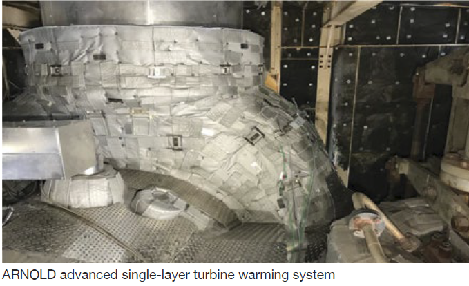
Ansmann and Gagnon explained that the ARNOLD system features interlocking high-performance blankets which conform perfectly to the turbine surface. High-quality materials and manufacturing, and long-term high-temperature resistance, allow the company to guarantee reuse of its insulation system for 15 outages without a decrease in efficiency.
More than five-dozen thermocouples, strategically located on the turbine, ensure proper heating. Each of the 18 or so heating zones has t/cs installed on the heating wires to double check if the zone is responding correctly and at the specified temperature. Below every heating zone, multiple t/cs are mounted on the casing to confirm even heating of the turbine.
The speakers said the ARNOLD warming system can maintain your turbine in a hot-start condition for at least four or five days after shutdown. No preheating of the turbine is required prior to a restart within this time period, reducing startup fuel consumption and auxiliary power.
Remote Monitoring of Lube Oil and Diesel Conditioning
Oil conditioners/kidney-loop filters are known for their ability to keep oil, and the machines relying on it, clean and healthy. In his presentation, Axel Wegner shows you how to keep lube and diesel oils in top condition; plus, how to receive alerts as soon as anything oil-related drifts out of spec—such as cooling-water temperature, excessive wear of machine parts, ISO particle count, etc.
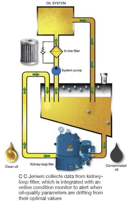
Wegner’s message is clear: The optimal condition-monitoring and filtration system for any machine and oil type allows you to identify problems remotely and to take action before they get out of control. This presentation is one you might want to consider sharing with your plant’s O&M staff during a lunch-and-learn session.
Essential Monitoring for Quickly Identifying and Repairing Air In-Leak Sources
Collin Eckel presented case studies highlighting a new process that combines repair of air in-leaks—identified through a condenser helium leak audit—and condenser vent-line air in-leakage measurements using the company’s Multi-Sensor Probe (MSP).
Recall that the presence of helium at the condenser exhausters indicates a leak. Intek’s MSP, installed in the vent line between the condenser and exhauster, measures and continuously calculates the condenser’s total air in-leakage rate.
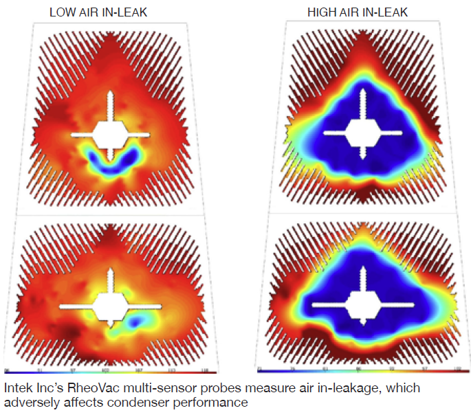
Data from the MSP allows users to narrow the search areas for potential leaks, thereby increasing the success rate for finding and repairing them, and reducing the time for doing so. As air in-leaks are repaired, the MSP’s air in-leak value indicates the size of the leak eliminated by subtracting the new value from the total air in-leakage rate recorded before the repair was made.
Solutions for the D11 Closure System, Coupling Bolts, and Casing Tensioners
Adrian Price discussed the company’s Boltight D11 closure system and casing tensioners, focusing on how these products can cut maintenance costs by reducing the time required for (1) accurate, damage-free bolting, and (2) the tops-on/tops-off process—from as much as several days to several hours.

Co-presenter Steve Busalacchi walked attendees through the EzFit coupling-bolt solution and its benefits: reduced downtime, accurate radial force, safer installation, and the ability to achieve preload with hand tools. He profiled recent cases demonstrating the technology’s value in the field; plus, the preemptive steps plant personnel can take to minimize flange-bolt faults in future maintenance situations.
Users reviewing Busalacchi’s presentation will benefit from a better understanding of the principles of mechanical expansion bolts—what they are, how they work, and how they mitigate the problems associated with fitted bolts.
 Parker Motion & Flow Control Products Inc
Legacy Denison EHC Hydraulic Pumps and Steam Turbine Applications/Support
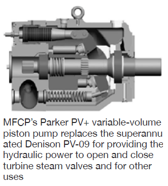
Steve Westmoreland, a senior design engineer at MFCP, had good news for users trying to get by with their Denison EHC pumps, typically used to provide the hydraulic power for opening/closing valves on steam turbines. The workhorse Denison PV-09, which dates back 70 years, is no longer offered. The pump is obsolete and parts are not available from Parker, which bought Denison in 2004. Plus, it is becoming increasingly difficult to rework existing parts.
Westmoreland introduced attendees to the Parker PV+ variable-volume piston pump, available in horizontal and vertical arrangements, as a replacement for the PV-09. The following benefits of the PV+ over the PV-09 were highlighted:
-
- The pump/motor interface is a simple bolt-together process; no laser alignment necessary.
- Response time has been halved.
- Higher efficiency (volumetric and mechanical).
- A hydrostatic saddle bearing/swashplate replaces wear-prone rollers and bearings.
- Improved suction characteristics—especially important to units operating at high altitude.
- Separate cooling/filtered-oil loop to cool shaft bearings and seal, and the hydrostatic bearings.
Advanced Crack Detection in Free-Standing Steam Turbine Blades
The risk of steam-turbine blade flutter increases at low loads and vibration monitoring can detect this condition, thereby allowing owner/operators to take corrective action with the goal of maximizing fatigue life. Think of this presentation as a primer on how blade vibration monitoring is implemented. It also discusses a proven technique developed by Siemens to detect cracks in free-standing blades.
Lifecycle Maintenance Planning and Execution for Reliability and Cost Control
The second presentation made in the Siemens breakout explained the company’s bid strategy and outage planning. The key message here was to begin planning as early as possible and engage the OEM’s experts, and others, to assist in decision-making.


