Decarbonization of the electric power industry will increase the use of hydrogen as a gas-turbine (GT) fuel—alone or in combination with natural gas. Issues for hot-section components when burning hydrogen include the following: increased flame speed, temperature, quenching distance, steam in combustion products (from 12% to 21%), and loading.
The resulting increase in erosion and heat transfer to base materials and coatings, and the durability of the thermal barrier coating (TBC) applied to hot-gas-path (HGP) components, is an industry concern.
A durability test was initiated by TEServices, La Porte, Tex, to determine if the following coatings can withstand a hydrogen environment: (1) Conventional yttria-stabilized TBC Y for mature gas turbines, and (2) Advanced rare-earth-stabilized TBC K for the latest GT models.
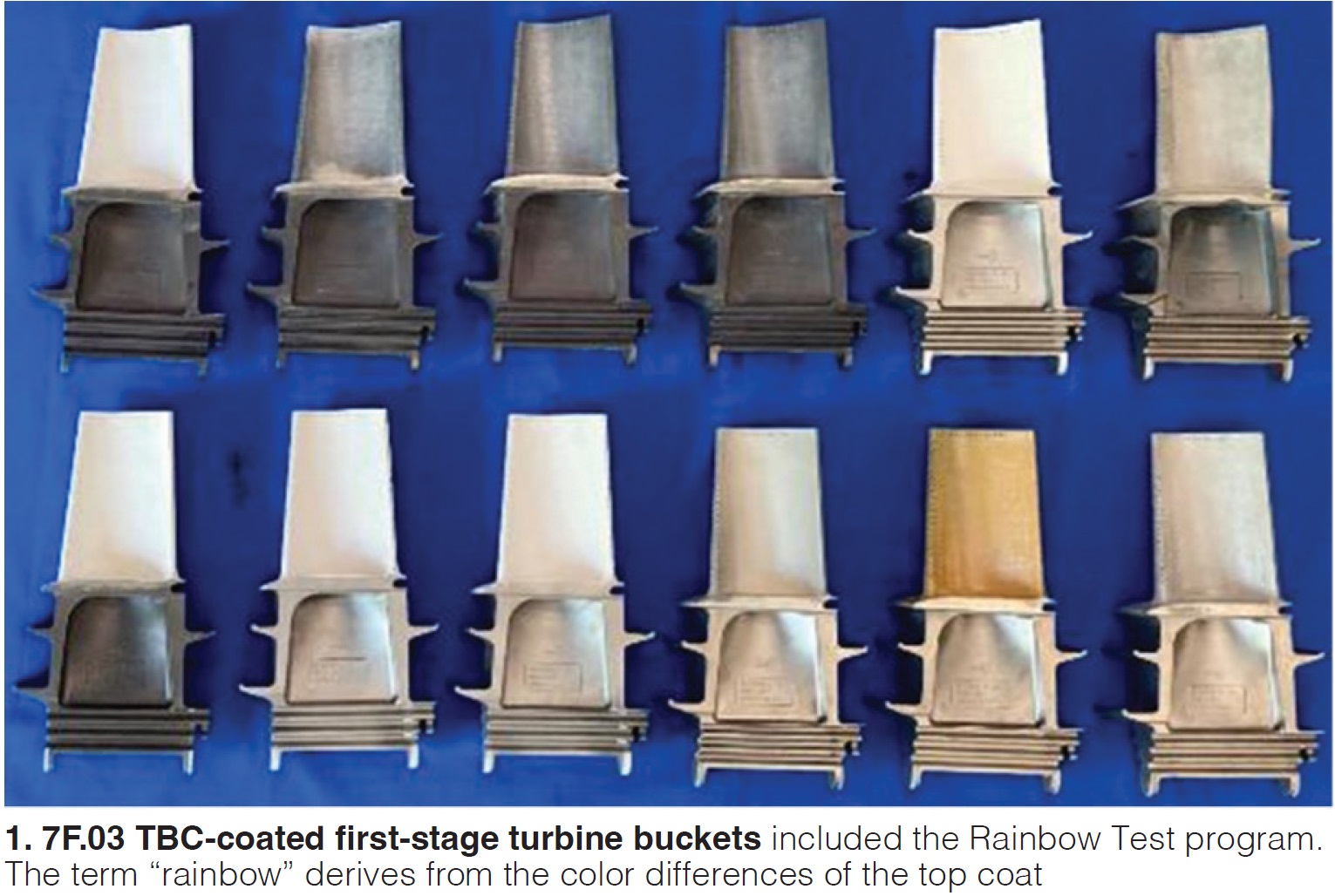
With Dominion as the host and EPRI the sponsor, eight participants (Honeywell, Liburdi, PSM, Cincinnati Thermal Spray, APG, Doosan, MD&A, and Sulzer, and the baseline OEM) provided a dozen different coating applications for this test. Five are conventional dense vertical cracked (DVC) TBC Y—including one OEM-applied DVC TBC—and seven advanced, combination DVC/TBC K coatings on GE 7F.03 first-stage buckets (S1B).
The initial borescope inspection provided promising results (Fig 1 and the table). This article is the first of five planned on the subject. Mission of TBC Rainbow Test I (2024) is to introduce the program, install the buckets, and provide the first borescope results. The remainder:
- Test II, with borescope results at the halfway point in the program (2023-2025).
- Test III, lab testing (phase change and thermal conductivity).
- Test IV, final borescope results (2023-2027).
- Test V, final results—including metallurgical evaluations, etc.
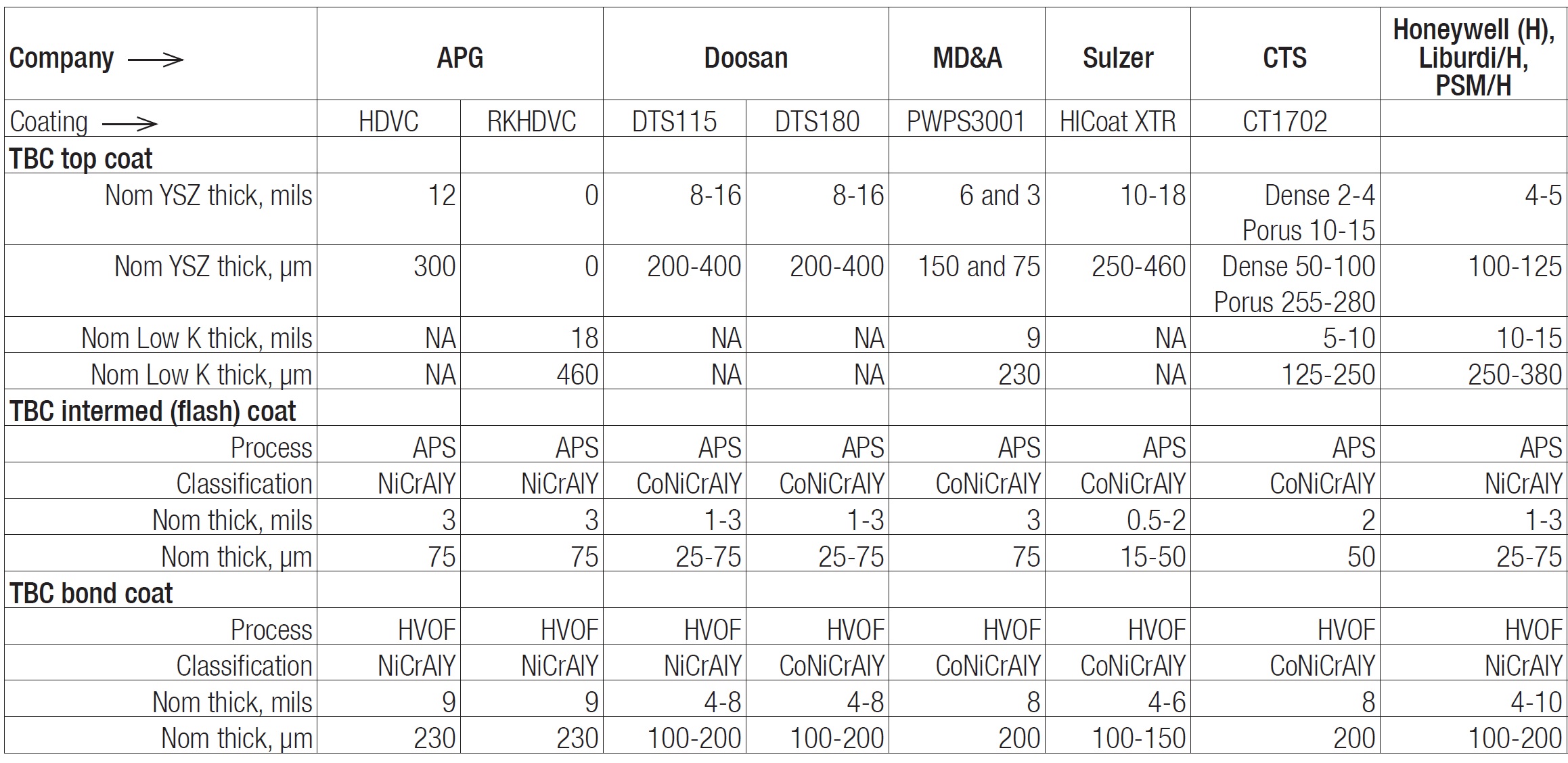
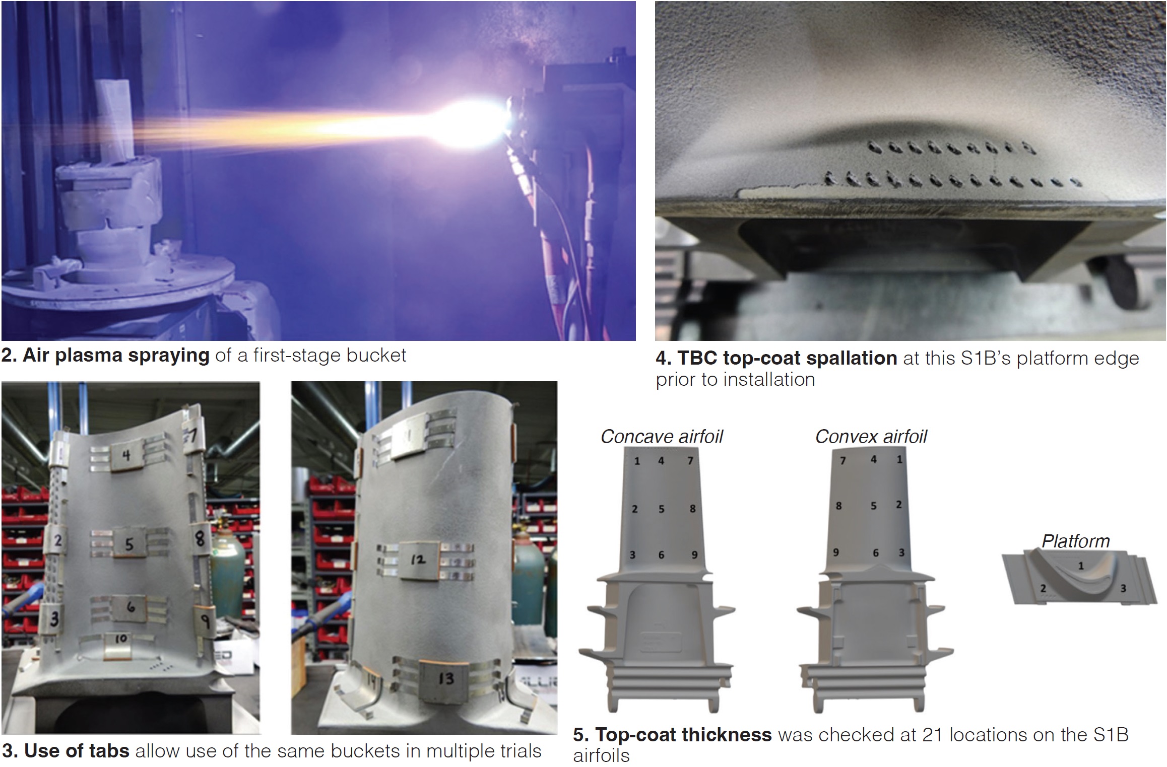
First-article inspection (FAI) on the actual parts must be performed to ensure the coating application will promote successful turbine operation. Recall that most conventional coatings currently are applied on 7F.03 S1B airfoils and other HGP parts; however, optimum thermal-spray settings and robotic programs had to be developed for advanced coating systems in this test (Fig 2).
Metallurgical evaluation of the bond (applied by high-velocity oxygen fuel, HVOF), flash (air plasma spray, APS), and top (APS) coat was performed for thickness, interface contamination, porosity and oxidation, vertical and horizontal cracks, unmelted particles, oxide clusters, and other imperfections. Fig 3 shows that most coating providers opted to use tabs attached to the S1B so the same bucket could be used for several trials.
The optimum thermal-spray settings and robotic program for part preparation, robot location, and part manipulator; fixturing and programming of the robot coded; and coating parameters and heat treatments were documented to ensure these steps could be repeated for the actual parts. Inspection reports and metallurgical samples were made available to TEServices and Dominion for review and qualification based on the coating specifications outlined in TEServices’ “7FA.03 Repair Specifications.”
Proper coating application on the actual GT components should be verified before their installation to avoid premature coating failure and the need to remove affected components.
TEServices’ verification included visual inspection, serial numbers, cooling-hole check, review of quality records including work scope, inspection reports with weight gain and ET thickness, and heat-treat charts. Visual inspection revealed three buckets with the same coating system as having spallation of the top coat at the edge of the active-side platform. The initial participant proposal was to flash coat these locations with a ceramic top coat and blend; however, after discussion with the coating participant, TEServices and Dominion decided to test these buckets as is (Fig 4).
Top-coat thickness was checked at 21 locations (Fig 5) using an eddy-current thickness gage to determine erosion and/or delamination of the top coat during operation. The average top-coat thickness of each coating system was between 8 and 22 mils (200 to 560 µm).
The S1Bs were blue-light scanned after stripping (Fig 6 left) and again after TBC application (Fig 6 right). The two scans were overlayed to determine the total (top, flash, and bond-coat) thickness based on the difference of dimensions in the airfoils.
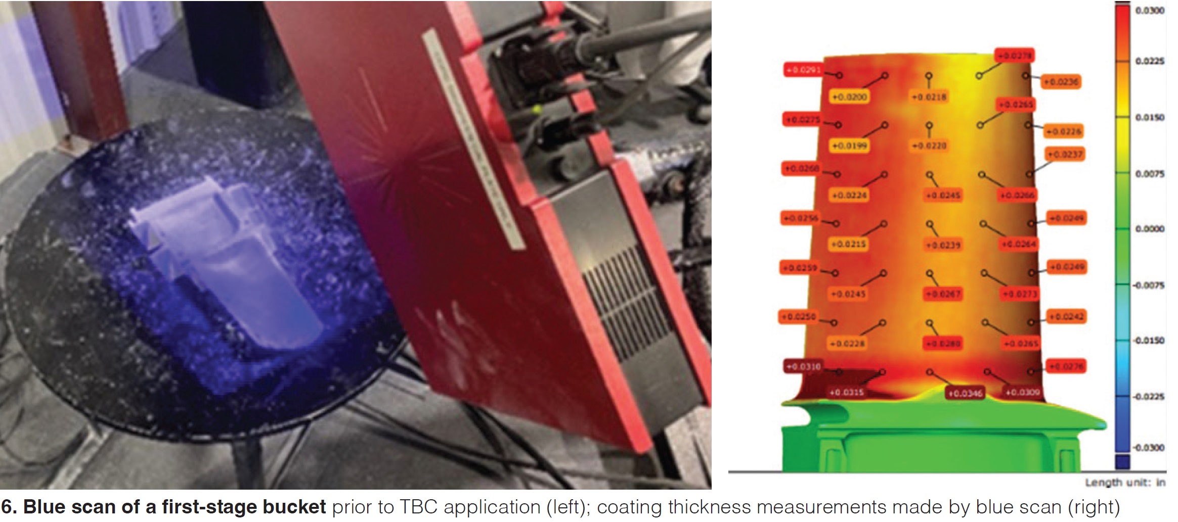
This was valuable information for the coating participants, allowing them to modify their robotic programs for future sets of S1B to obtain a more uniform coating thickness. For the rainbow test, the value of this inspection comes after operation, to identify if delamination and/or erosion had occurred and if coating thickness was a contributor.
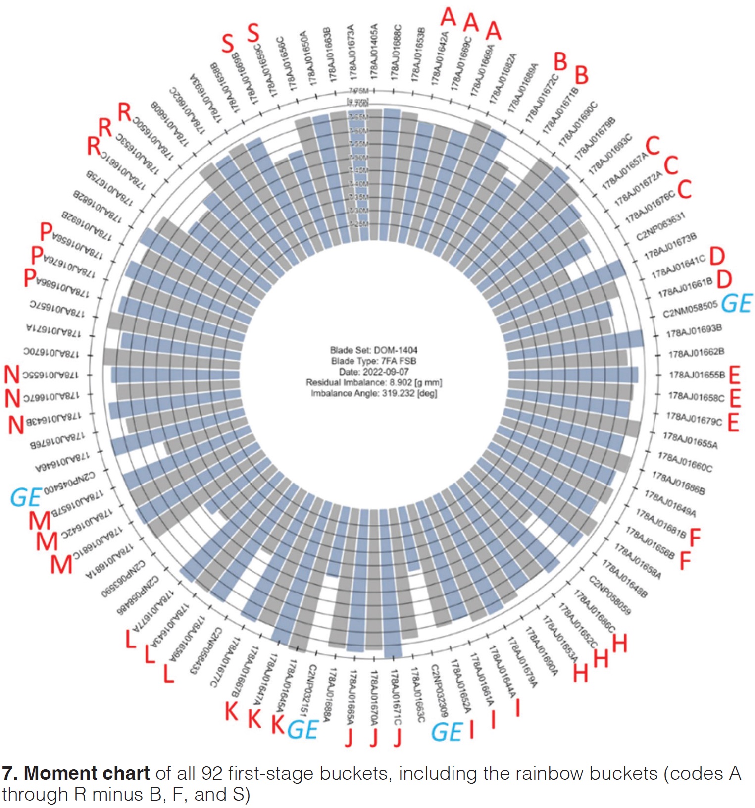
Post-coating operations, installation. Prior to their installation, test buckets were shipped to MD&A for another visual inspection, cooling-hole check, flow check, and moment weighing and sequencing with the rest of the set (Fig 7).
Air flow was less than before coating; however, all flows met the MD&A minimum requirement of 0.0300 in² effective area, except for two buckets. Both were just below the requirement and accepted after engineering review.
All first-stage buckets were moment weighed and the sequencing was performed in a manner that the buckets with the same coating were grouped together for borescope purposes. This resulted in somewhat higher-than-normal residual imbalance (nearly 8 gmm) but still within MD&A specs and accepted by Dominion.
In November 2022 this set was installed in Dominion’s Chesterfield 7F.03 unit, which has a flared compressor and MNQC (steam injection) combustion system. Operation started the following month with these operating parameters: firing temperature, 2350F; steam load, 100,000 lb; and an estimated 800,000 lb/hr of air. Test duration is five years; planned removal is fall 2027.
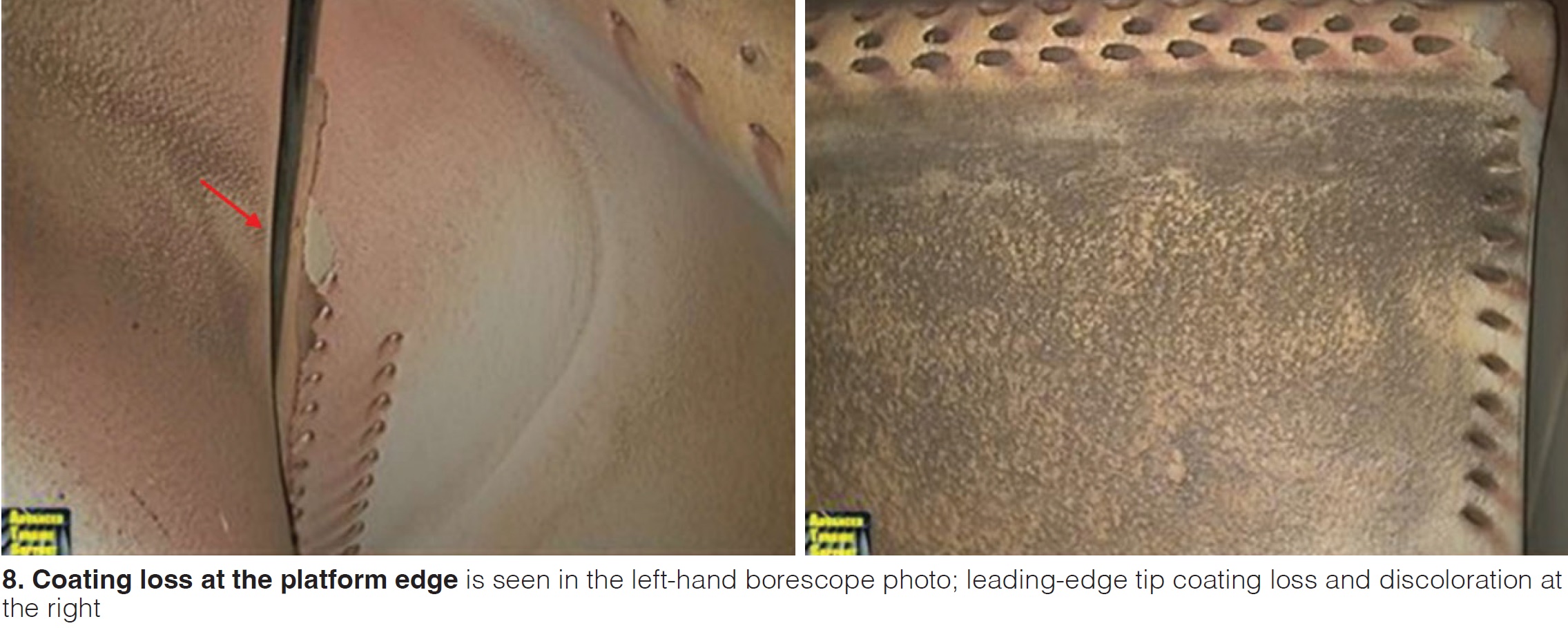
Semi-annual borescope inspections will be performed until removal of the first-stage buckets in 2027. The first borescope inspection was performed after 2000 hours in May 2023 by Advanced Turbine Support (Fig 8). The results of borescope inspections of all 92 first-stage buckets, including the repaired S1B with standard coating, are the following:
- No defects detected in 67 buckets.
- Leading-edge tip spallation in five buckets.
- Minor leading-edge cooling-hole spallation in one bucket.
- Severe leading-edge cooling-hole spallation in five buckets.
- Leading-edge and platform spallation in three buckets.
- Spallation of the leading-edge tip and mid cooling holes in three buckets.
- Color difference in three buckets.
The bottom line: TBC applied on all first-stage buckets was able to withstand the hydrogen environment for the first 2000 hours. Next year, following TBC Rainbow Test II, TEServices will report the halfway (2023-2025) borescope results.
Acknowledgement. This article is based on “Durability Test of Advanced TBCs,” presented at ASME Turbo Expo 2024, held June 24-28, in London, England. Authors were Hans van Esch and Stijn Pietersen of TEServices, John Scheibel of EPRI, and Olaf Barth of Dominion Energy.


