Overfiring during startup
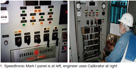
General Electric Speedtronic™ Mark I control systems were installed on gas turbines in the early 1970s, primarily on MS5001N and MS7001B engines. Fig 1 shows a typical Mark I panel being tested using a device known as the Speedtronic Calibrator. Note that the Calibrator has two ribbon connectors patched into designated locations and that the engineer is using digital voltmeters.
Case history. The owner/operator of a Frame 5N near Houston called PAL Turbine Services on a hot summer day and reported that its engine would “hang up” during startup when the speed reached about 1800 to 2000 rpm, well below the operating speed of 5100 rpm. Troubleshooting actions taken for the symptoms described on the phone had been unsuccessful. The situation was dire, the user said; power from this unit was needed urgently.
PAL General Manager Dave Lucier told the editors, “As good luck would have it, I had a set of Mark I turbine elementaries and control specifications with me. I accessed the Internet from my car, parked outside a hardware store, booted up my computer, called the plant operator, and then walked him through some troubleshooting techniques.
The turbine was shut down at the time. “I asked the technician, who had a millivolt source, to connect it to a particular amplifier associated with an analog output from the 12 control thermocouples (Fig 2). He found the gremlin, a blown 240F oven (Fig 3).

“With no spare on hand, I suggested that the technician borrow one from either OTA or OTB until we could supply one. Recall that the control card has three similar ovens. Inside the black box in Fig 2, there are these three so-called reference ovens:
-
- Average temperature control (TC-1 through TC-12); it creates signal TXA, a/k/a average exhaust temperature.
- Over-temperature control A (T1, T3, and T5); it creates signal
- Over-temperature control B (T2, T4, and T6); it creates signal
Other points to remember: GE temperature control and protection systems are not referenced to 0F. The output signal must exceed 240F before the analog output signal goes “positive.” Also, TXA, OTA, and OTB are “compared” for over-temperature protection. A disparity of about 50 deg F among the three temperatures triggers an alarm. Additionally, if OTA or OTB exceeds 970F an alarm occurs; at 1000F, the turbine will trip and shutdown.
TXA is one of the functions that can “control” the voltage signal, hence fuel flow to the combustors. During turbine startup, there are three “competing” controls that can take charge of the command voltage signal called VCE, a/k/a variable control electronic (Fig 4, right).
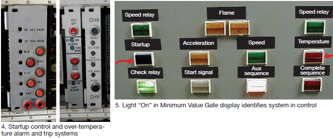
This is known as the minimum value gate MVG (Fig 5). Lights in the middle row of the photo identified by red arrows are the controls that can limit and lower the VCE voltage to control fuel flow. A light is “On” when in control.
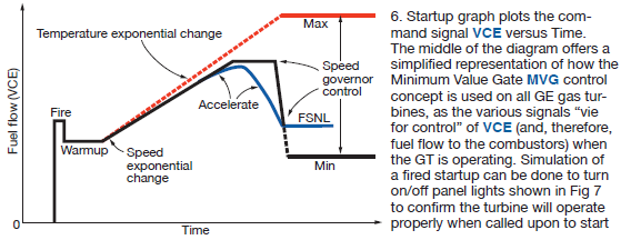
During turbine startup (Fig 6), the following control variables can limit (or reduce) VCE and, therefore, limit fuel flow to the combustors:
1. ACCEL VCE limit. Default. High limit at 8.5 V when no other takes control. Blue light.
2. Accelerate exponential (VCE rate of change—0.2 V/sec. Adjustable on card.
3. Acceleration control—approximately 50 rpm/sec. Not adjustable on card. Yellow light.
4. Temperature exponential change (TXA rate of increase)—5 degF/sec. Red light.
Returning to the starting problem in Texas, it was determined that the 240F oven for the TXA reference failed because it overheated. Lucier continued, “To get plant personnel through the crisis, I asked the technician to unsolder the failed oven and install the OTA oven until we could provide the plant with a spare (used) card. In the meantime, operators would have to live with a continuous exhaust-temperature-differential alarm.
Lesson: It helps tremendously to understand the “normal operation” of GE gas turbines with Speedtronic Mark I control and protection systems. If you don’t know how the system is supposed to work, how can you recognize “abnormal” operating conditions.
Startup simulation
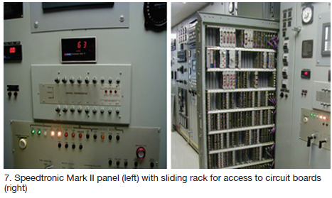
Speedtronic control systems provided with GE gas turbines from about 1970 to 1985 included two generations of controls designated Mark I, discussed above, and Mark II. Hundreds of these packaged powerplants were installed worldwide during that period, most with Mark II controls (Fig 7).
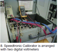
The focus here is on the Speedtronic Calibrator (refer back to Fig 1), which can be used to simulate a startup without firing the gas turbine. This could be useful to simply demonstrate that a startup likely would be successful, or perhaps when fuel is unavailable for some reason, or if emissions are of concern.
Signals can be created on the Calibrator using the power supplies from the panel. Once plugged in at the proper locations, four final regulators on the Speedtronic panel are sent to the Calibrator.
For the Mark I they are the following:
-
- +12 V dc (for digital signals).
- +28 V dc (for panel relays).
- +50 V dc (analog signals).
- -50 V dc (analog signals).
 For the Mark II on MS5001N and P, and MS7000B and C, engines:
-
- +6 V dc (for digital signals).
- +28 V dc (for panel relays).
- +12 V dc (analog signals).
- -12 V dc (analog signals).
The Calibrator has red and blue ribbon connectors, each with 51 pins, similar to the circuit boards on the Speedtronic panels; the Calibrator should be connected only to specific dedicated slot locations.
A “patchboard” is provided to jumper signals to the appropriate circuits, as well as to connect digital voltmeters (Fig 8). Resistors on the right side of the Calibrator allow for adjustments of speed (NHP), temperature (TXA), and another dc voltage source for pressure signals (PCD or P2).
The basic tasks for simulations fall into the following categories (with GE signals designated):
1. Speed signal NHP—0 to 100% (5100 rpm on Frame 5N or Frame 5P).
2. Speed signal to energize speed relays—14HR, 14HM, 14HA, and 14HS.
3. Digital setpoint (DSP) for speed control and speed droop, referred to as the “called-for” speed.
4. Exhaust temperature (TXA) for temperature control simulation.
5. Pressure transmitter simulation (PCD)—voltage signal proportional to air pressure.
6. Gas fuel pressure (P2) for fuel controls—voltage compared to NHP.
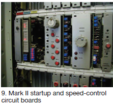 Fig 9 shows Row 1 of the Speedtronic panel, which holds the startup and speed-control circuitry. Other rows hold the cards for turbine operation. The Calibrator can send signals to various circuits for simulation, as desired. A trained engineer or technician will find useful the techniques provided in the GE control specifications and other training documents.
Wrapping up, simulation is a good way to test Speedtronic Mark I and Mark II gas-turbine controls using the OEM’s Calibrator. This saves time and fuel when actual turbine operation is undesirable.


