Turbine Tip No. 12 from the PAL solutions library applies to General Electric package power plant (PPP) models MS5001D, L, and LA.
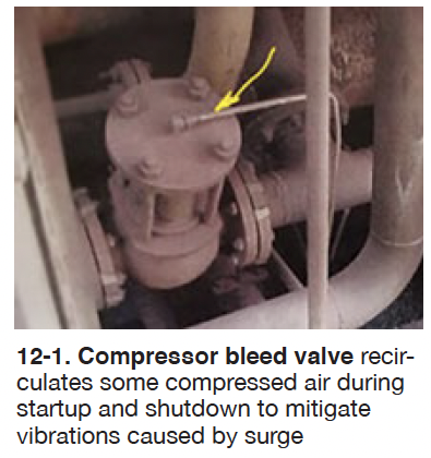
GE installed compressor bleed valves (a/k/a recirculation valves) on these legacy gas turbines. Axial-flow compressors for the earliest units—those with 15 or 16 stages—had valves to recirculate air from the 10th stage to the fourth, for “unloading” the machine during startup and shutdown to mitigate vibrations caused by the surge phenomenon. Two valves were installed for this purpose in the turbine compartment adjacent to the compressor casings (Fig 12-1).

Later turbine models, those with 17- and 18-stage compressors, were equipped with valves to bleed air from the 11th stage to the turbine exhaust during startup and shutdown.
The recirculation valve shown in Fig 12-1 is open during startup and shutdown and later closed by compressor discharge pressure tapped from the 16th stage via the small line on top of the valve (arrow). Depending on spring strength, the valve is fully closed at a PCD of about 30 to 40 psig. Note that the acronym for compressor discharge pressure, PCD, as found in early instruction books, was changed to CDP in the mid-1980s.
These recirculation valves do not have position “indicators.” If either or both valves should remain hung-up in the open position during online operation, performance (turbine power output) would suffer, because air flow to the combustors would be lower. However, no damage to the compressor should be experienced even if not fully closed when the unit is online.

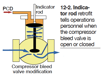
My late former partner, Charlie Pond devised a simple solution to assist operators in knowing whether the valve is open or closed (Fig 12-2):
- Remove the valve cover and drill a 9/16-in.-diam hole in the top beside the PCD tubing line.
- Relieve the hole opening to accommodate an O-ring.
- Determine the length of rod to be used as the indicator and mark it for the fully open and closed positions.
- Select an appropriate O-ring to help seal the rod from excessive air leakage.
- Grease the rod and O-ring, making sure the rod moves smoothly as the valve strokes from open to closed.
- Install a pressure gage in the PCD supply line.
Note that it’s best to test the valve travel while the gas turbine is shutdown.
Endnote: As Pond would often remark, “Sometimes the simple solution to a problem is best.”


