An hour’s investment pays dividends in cost-effective controls upgrades for vintage gas turbines, TTS Power.
If your site has a pre-F-class gas turbine, in peaker or combined-cycle mode, and you think there’s more money to be had playing the spot-capacity or flexible-start markets, take an hour and listen to TTS Power’s recorded webinar conducted a couple of weeks ago. Chances are, you’ll come away with an option that not only makes sense but also is affordable.
For optimizing capacity to meet the spot market, the options include raising firing temperature, increasing mass flow, implementing dormant peak-firing capability (that is, originally designed into the unit but not used), and optimizing peak firing (especially for DLN units).
Most of these require a thorough evaluation of the unit’s current operating regime compared to original design. The outcome can be as simple as discovering that the current firing temperature is what satisfied the commissioning criteria, not the GT’s capability; or as complex as learning that mods deployed to increase mass flow (wet compression, for example) did not properly optimize for firing temperature.
The key, noted Ricky Morgan, TTS Power’s VP engineering, during the Q&A, is to ask yourself, “where could this machine fire,” not assume that where it currently is firing is optimum.
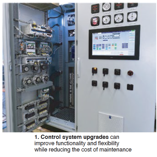
Only a few vintage GT designs can meet 10-min start requirements without mods, noted VP Pat Begley. The biggest gain comes from eliminating the purge cycle via NFPA 85, but smaller gains—such as by upgrading wiring and cabling, replacing hydraulic/pneumatic valves with electric, eliminating single points of failure in transmitters, sensors, and switches, upgrading HMI, and otherwise replacing obsolete components—can add up (Fig 1).
The impact of any of these mods on GT maintenance factors and the site’s emissions permit must of course be thoroughly evaluated. Plus, the more “vintage” a machine is, the more likely it is to be operating off of original design, if only because of deferred maintenance and component changes. Thus, you’ll want to have a site evaluation study once you identify one or more options that could make sense.
How to straighten a bowed steam-turbine rotor, MD&A.
When you’re sick, or something seems “off,” what do you do? Many people search the web,
often arriving at a WebMD, Mayo, or equivalent site, for some initial information. If symptoms persist, you go to your primary-care physician. The doc may tell you to see a specialist or even a surgeon.
Thankfully, when your steam turbine seems “off,” and you suspect the rotor, you can get “integrated care” from the 500 folks at MD&A, including 200 seasonal traveling turbine experts. Who says doctors don’t make house calls?
Think of the “Bowed Rotor to Straight Rotor” presentation by Rob Kilroy in MD&A’s Spring 2021 Webinar Series (February 16), summarized here, as WebMD. If the turbine rotor needs an official diagnosis, MD&A will send inspection specialists to your site. If the diagnosis suggests repairs, the company will handle those as well.
If you are recording a gradual increase in rotor vibration over a long period, it may be time to listen up. The rotor may be bowed, caused by persistent asymmetrical heating or cooling of the shaft. Pre-1960s turbines rarely experienced bowing. Today’s longer, more slender rotors with a reduced number of bearing pedestals and more aggressive operating parameters are more susceptible.
The MD&A crew is seeing around a dozen bowed rotors each year. That may not seem like a lot, but given the damage a bowed rotor can do, it’s best not to find out the hard way.
In the webinar, Kilroy explains rotor bowing is defined by the total indicated reading (TIR). If the TIR is less than 0.03 in., the bowing is minor, if between 0.04 and 0.015 in., it’s moderate, and above 0.016 in., consider it severe. Severely bowed rotors typically cannot be balanced, and will require an engineered straightening solution.
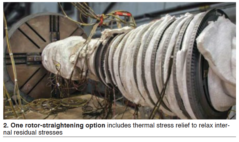
The turbine/generator repairs engineer delineates three categories of straightening options, once the detailed in-casing and disassembly inspections are completed: Machining/throwing of journals, stress relief/heat lathe, and thermal straightening (Fig 2). The last two typically do not require resizing of the bearings.
Best of all, Kilroy reviews seven case studies, the first three on the cusp of severe with max TIRs of 0.015. In general, the “surgeries” MD&A performed return the rotors to a TIR of between 0.001 and 0.005. In one case, a rotor with “all kinds of problems” and a 0.007-in. TIR at the turbine end and 0.053 at the generator end, MD&A’s solution reduced the TIRs to 0.001 in. at both ends.
Rotors from a variety of manufacturers are featured in the case studies. Frequently, the rotor was subjected to multiple straightening options and ancillary machining and component replacements. You’ll understand the innovative thinking that’s required once you watch the video (users only). Simply click the QR code to gain access.
Diaphragm dishing most severe in steam turbines installed during the last three decades, MD&A.
The “Diaphragm Dishing Issues” presentation by Steampath Engineer Jeff Newton in MD&A’s Spring 2021 Webinar Series (February 18) addressed permanent axial distortion of steam-turbine diaphragms, commonly known as dishing. The effect is usually caused by deficiencies in main weld depths, weld materials, welding processes and/or steampath design with the maximum movement at the horizontal joint where the diaphragm is weakest, according to Newton.
Unless you are already an expert on steam-turbine condition, you’ll want to see the photos shown during the presentation to get a good sense of dishing (not to be confused with thermal distortion) indicators, including: outer-ring distortion, evidence of main structural weld failure, reduced axial clearance at inner setback face, rubbing, packing high teeth out of location, horizontal-joint gaps larger on the discharge side, and packing bore diameters larger on the discharge side.
If you think you have a weld failure, get a second opinion quickly; that will require immediate repair, says Newton.
Steam turbines of 1950s to mid-1960s vintage typically experience the worst dishing in the third reheat stage. That’s because it is the highest-temperature stage with carbon steel used as the seal weld material between the partitions and spacer bands, notes the steampath engineer. The condition is more prevalent after 40 years of operation; the expected design life of turbines from that vintage was 30 years. There also was a better pool of data because steam turbines underwent major inspections and outages every five or six years.
However, it is important to note none of the diaphragms from this time period actually failed, stresses Newton.
Things get dicier beginning in the 1990s. At least one manufacturer began to replace submerged arc welding in these areas with electron beam and MIG welding, which led to less consistency in weld quality; the CrMoV (chromium, molybdenum, vanadium) metallurgy was changed to just CrMo; dense-pack designs led to more stages with less axial space; and diaphragms were not as thick. Main weld depths as a percentage of partition axial height also were reduced. Furthermore, the time between major outages was extended to more than 10 years.
These units have experienced diaphragm failures (Fig 3). One Toshiba unit failed within five years at the first IP stage. In fact, the three examples Newton reviews are all Toshiba. A second unit also failed at the first IP stage; bucket and rotor material were found missing at disassembly.

Three of the ways to proceed if you have evidence of dishing are do nothing and monitor, install offset packing rings, and/or shift the diaphragm upstream with a steam seal face insert. However, Newton stresses, these do not address the cause of the dishing. The component has to be reconstructed, or reverse engineered with design changes to address the cause (Fig 4).
Newton illustrates this for users with a photo montage sequence that drives home the as-found versus repair comparison. Simply click the QR code to gain access.
Maximizing the lifetime of gas-turbine hot parts, MD&A.
If you’re having difficulty with your F-class gas turbine OEM when it comes to repair of hot- gas-path (HGP) components, MD&A wants you to know they not only have the experience you are seeking, but also enhancements, which will extend service life, plus better transparency and customer oversight throughout the repair process.
In the “Extending Service Lives of Gas Turbine Components” segment of MD&A’s Spring 2021 Webinar Series (February 23), Director of Engineering Jose Quinones, PE, reviewed the company’s capabilities, experience, and customer-care process, most pointedly through eight examples, including nozzles, blades, and shrouds for F-class GT stages 1-3 nozzles.
Key takeaway: Don’t sell “scrapped” HGP parts until you let MD&A look at them. Watch to the end of the webinar (users only) and you’ll see why. Simply click the link to gain access.
MD&A’s sweet spot with these types of repairs is “single-crystal components where users have difficulty getting service.” All steps of the repair process are done in-house except a hot isostatic press and an internal aluminide coat, if necessary.
Several “gates” are established during the repair sequence for process and quality reviews with the customer. As just one example of an enhancement, MD&A adds silicon, hafnium, and other elements to the thermal barrier coating which reduces surface degradation and crack propagation (Fig 5).
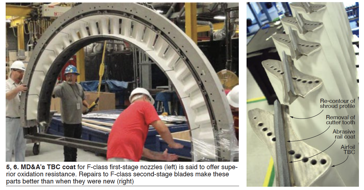
Perhaps the most captivating part of the webinar was when Quinones discussed how MD&A repairs components deemed “unrepairable” by others, such as, in one example, second-stage nozzles with creep deflection, cracks, oxidation, and clearance reductions. In this case, the cooling holes were exposed because of thinning (Fig 6).
Quinones explained that there may not have been repair techniques available when some parts were sent to the graveyard. In an astonishing case, MD&A took components worth $7600 as scrap, repaired them for $1.3-million, and saved the customer many millions more.
As noted during the Q&A, best to loop your insurance company into the conversation regarding such repairs, especially when MD&A’s assessment is different from the OEM recommendations.
Stator repairs in the spotlight, MD&A.
If you are not a generator specialist, the things you probably need to know about stator wedges are that they hold the stator bars in the iron, there are lots of them (1200-1800), and they can loosen from age or unusual or persistent vibrations, which interrupts electrical contact, leading to spark erosion. Testing them for tightness is labor-intensive, and re-wedging, if necessary, can extend the outage by up to eight to 10 shifts.
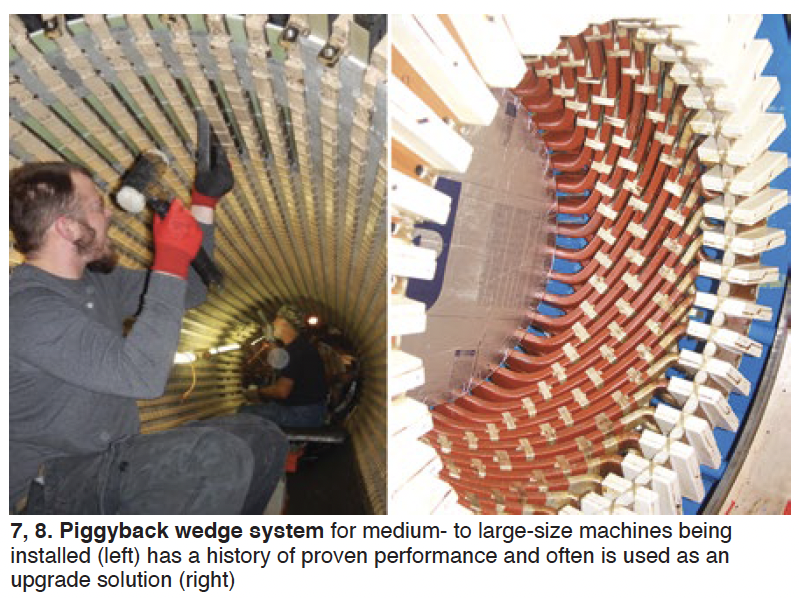
“Generator Stator Wedge Issues,” included in MD&A’s Spring 2021 Webinar Series (February 25), discussed by Generator Operations Manager James Joyce, offers a primer on the different types of stator wedges for machines made by different OEMs; inspection techniques; some of the nuances of tightening and re-wedging, such as maintaining core compression nuts at optimum torque value; and wedge-system enhancements—such as replacing flat wedges with the company’s piggyback design (Figs 7 and 8). Simply click the QR code to gain access.
Guaranteed emissions compliance for ageing gas turbines, Noxco.
Jeff Bause, Noxco’s CEO, opened the webinar by explaining to turbine users how his company is raising an industry bar with the first LTSA (long-term service agreement) for emissions compliance. He said that by removing the burden and responsibility for protecting and managing complex systems from owner/operators, Noxco delivers performance, predictability, cash flow, and 100% risk mitigation through a turnkey solution.
Bause is well-known to many CCJ readers for his deep knowledge of catalyst system maintenance, gained over the years as CEO of Groome Industrial Service Group. He is a frequent speaker at industry events on SCR and CO catalyst cleaning, repacking, and replacement, plus the cleaning of ammonia vaporizers and injection grids, as well as of HRSG tubes.
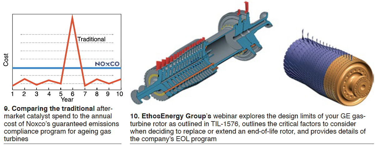
Noxco’s turnkey solution, Bause says, increases the operational flexibility and performance of the SCR, CO catalyst, and ammonia injection system (AIG) to deliver sustained peak performance at the lowest lifecycle cost (Fig 9). LTSA benefits include all system maintenance, inspections, tuning, optimization, catalyst testing and cleaning, catalyst replacement with the optimal product for your site and operating conditions, spent catalyst disposal, AIG design optimization and tuning, and performance upgrades. Access the recorded webinar to get the details.
Your GE gas turbine can run longer: What to do when your unit is reaching the designed rotor end-of-life limit, EthosEnergy Group.
If your plant is equipped with a GE industrial gas turbine—Frame 3, 5, 6, 7 (A, B, C, E, EA, and/or F)—and mention of the OEM’s Technical Information Letter 1576, “Gas Turbine Rotor Inspections,” does not strike a responsive chord, obtain a copy today from your plant’s GE representative.
TIL-1576, released in 2007 and updated in 2011 (1576-R1), identifies the equipment and personnel risks associated with operating gas-turbine rotors beyond 200,000 factored fired (FF) hours (144,000 for F-class units) or 5000 FF starts, whichever comes first, when specific intervals are not defined (Fig 10).
This TIL refers you to GER-3620, “Heavy-Duty Gas Turbine Operating and Maintenance Considerations,” for overall guidance on centerline maintenance recommended by the OEM. The latest version of 3620 is Rev N, important because it considers the impact of forced cooling on rotor inspection calculations, replacing the “trip from load factor” in earlier versions.
Kale Dreymala, GT rotor project manager, and Jeff Schleis, product manager, walked webinar participants through the inspection scope recommended by EthosEnergy Group (EEG) for turbine wheels, distance piece/spacers/stub shaft, and compressor wheels. Here’s the lineup of inspections typically recommended:
- Compressor and turbine wheels
- Visual inspection of all surfaces.
- Semi-automated phased-array ultrasonic (UT) inspection of the bore, web, and rim areas.
- Semi-automated eddy current (ET) inspection of the through-bolt holes.
- 100% ET inspection of the dovetail serrations in the compressor wheels and the fir-tree serrations in the turbine wheels.
- Distance piece, spacers, stub shaft
- Visual inspection of all surfaces.
- Semi-automated ET inspection of the through-bolt holes.
- Semi-automated phased-array UT of the bore.
Other inspections
- Dimensional measurements.
If these inspections produce no findings, the rotor is reassembled with new bolts and your engine receives a certification for an additional 50,000 FFH (one time only).
If there are findings, the speakers say the OEM is likely to suggest buying a new rotor or possibly a replacement wheel or disc, if that is the life-limiting part.
By contrast, an affordable aftermarket solution suggested by EEG probably would be to obtain a used rotor with a documented history and refurbish it in the shop. The additional life certified (from 50,000 to 200,000 FFH) depends on an engineering review. Note that for peaking units, no extensions are allowed beyond the 5000-starts limit.
The speakers also describe EEG’s capability for manufacture and qualification of new rotor components as might be required during the refurbishment process to get the best balance between cost and additional life. Other rotor options also were presented during the webinar, which was not recorded. However, you can write Dreymala for a copy of the presentation at kale.dreymala@ethosenergygroup.com. CCJ


